
Tutorials
FPGA UART Baud Rate Error: Compare Dividers Before Blaming the Cable
Published · Updated
State what the divider produces
A divider that generates one enable per transmitted bit differs from a divider that generates sixteen receive sampling ticks per bit. Write the oversampling factor explicitly. For an integer divider N, the simple model is actual baud=clock/(N×oversampling). Check the adjacent integer candidates instead of assuming ordinary rounding always gives the smallest baud error.


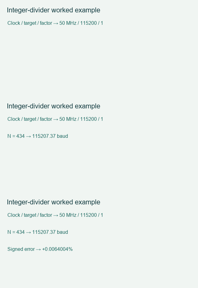
At 50 MHz with a target of 115200 baud and one tick per bit, N=434 produces about 115207.37 baud, or +0.0064%. A counter that runs from zero through N inclusive divides by N+1 instead. This off-by-one mistake is easy to hide when a testbench shares the same divider expression as the design.
Board bring-up sequence: Prepare the board checks before testing this interface.
I/O count and allocation: Reconcile signal count and physical allocation.
Budget both endpoints and the frame length
The transmitter and receiver do not share a clock on a basic UART link. Their relative rates determine how sampling drifts after start-bit detection. Oscillator tolerance, divider error, receive phase detection and the receiver sampling scheme all consume margin. There is no single universal percentage that certifies every UART implementation.
Record the frame format and the receiver specification. Include both endpoints at their relevant frequency extremes, not only nominal FPGA clock frequency. An oversampling factor changes the tick-divider calculation and can affect phase resolution; it does not remove clock tolerance. A logic-level UART connection also needs compatible voltages and a common reference. It is not a direct RS-232 connection.
External input/output timing: Include the external path in the timing budget.
Clock-domain synchronization: Keep asynchronous sampling separate from interface logic.
Measure bit duration independently of the RTL formula
Use a known transition-rich pattern to inspect bit duration and frame boundaries. Compare the observed rate with the intended divider and the clock actually present on the board. Verify reset, continuous frames and receive framing-error behavior instead of relying on one terminal echo.
The calculator compares the two adjacent positive integer dividers. It reports rate error without labeling it a guaranteed pass. Export the clock, oversampling and selected divider, then add the receiving device tolerance evidence. If a fractional accumulator is used, analyze its tick distribution separately; the integer-divider estimate does not describe cycle-to-cycle jitter.
Power-on test record: Retain the power states and test sequence.
Use the equations and review steps above. Interactive checks require JavaScript.Watch the short integer-divider worked example sequence
Save the check result with your exact device, board revision and unresolved conditions. Discuss the interface requirements when the remaining issue needs a board or implementation review. Opening this link does not submit the worksheet.
Sources and example scope
- determining-clock-accuracy-requirements-for-uart-communications.html
- Digilent Basys 3 rev. C Reference Manual
Documentation checked 17 November 2026. Worked values are illustrative calculations. No board measurement or Vivado implementation run is claimed. The worksheet checks entered assumptions and does not inspect your schematic or project files.
Back to Tutorials