
Tutorials
JTAG IDCODE Mismatch: Check the Device, Chain and Bitstream
Published · Updated
An IDCODE mismatch is a comparison between a value that was expected and a value that was read. Preserve both before changing anything. A stable but unexpected value, a value that changes between scans, and a bitstream built for another device require different investigations. Treating all three as “the wrong FPGA” can send a working board through unnecessary rework.
The comparison tool below accepts two raw hexadecimal values and retains their source and chain position. It performs an exact comparison, without silently masking revision bits or guessing a full ordering code. Its result is deliberately narrower than a component identification or authenticity report.
Open the diagnostic worksheet ↓
Separate the marking, scan identity and image target
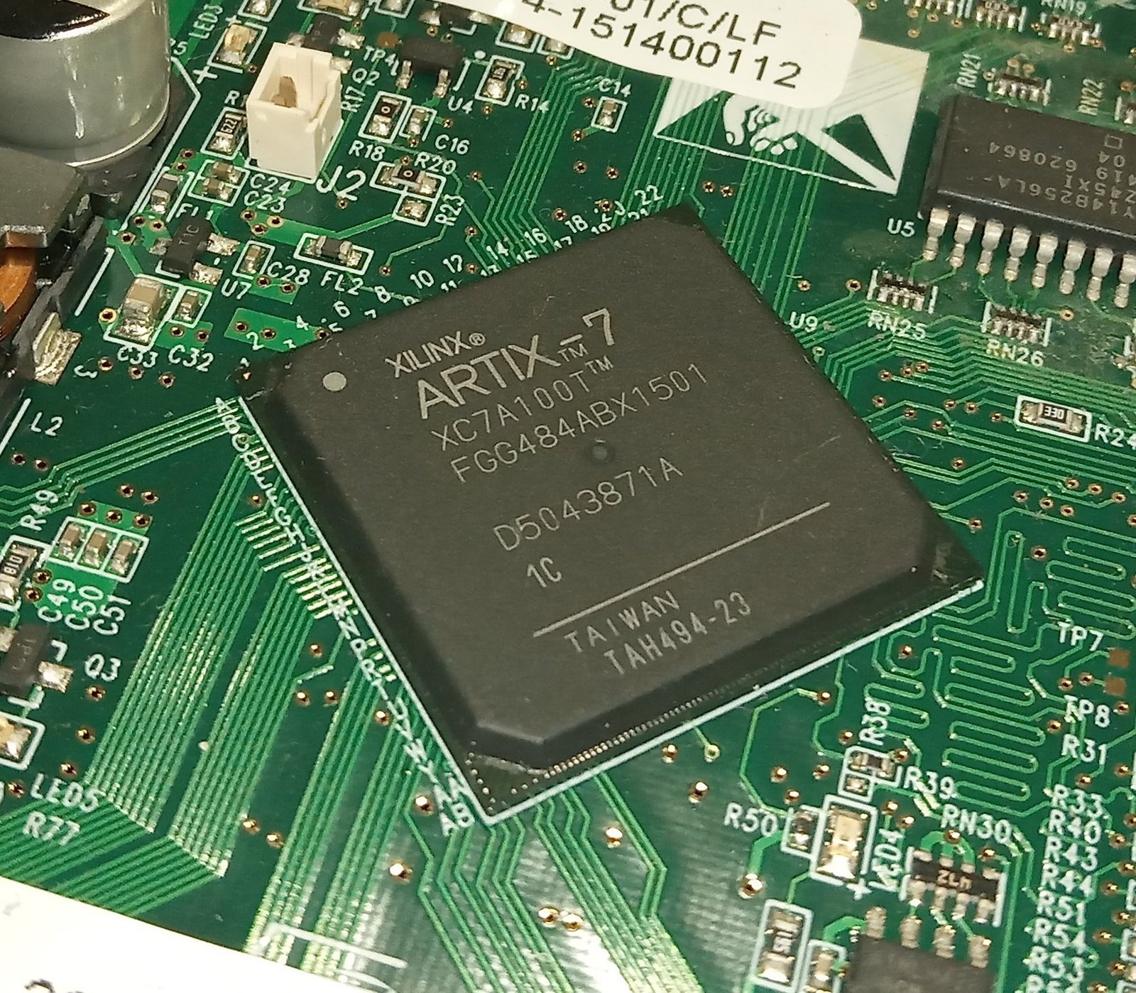

Begin with three records: the device fitted to the board, the device reported by the scan, and the target selected when the image was built. Photograph the package marking and record the board revision and assembly reference designator. Then capture the scan result and the full mismatch message. Finally, inspect the project or release manifest that produced the programming file. Each record answers a different question.
The real Artix-7 photograph illustrates why retaining a full marking matters. The device family and density are only part of the label. Package and grade information belong in the board and procurement record, even when the scan tool reports a shorter device name. The XC7A100T-1CSG324C catalogue page is a separate package-specific entry; the pictured FGG484 part should not be represented as that ordering code.
An IDCODE is not a substitute for the complete ordering record. A successful match does not prove package footprint, speed grade, temperature grade, supply history or authenticity. It also does not prove which application design is running. Keep those questions separate rather than asking one 32-bit observation to support every conclusion about the board.
Obtain the expected value from the manufacturer documentation for the actual device. Record the document version and table, including any revision-field conventions. A value copied from another engineer’s screenshot may refer to a different device revision or chain position. The comparison worksheet deliberately avoids a built-in identity database so that the expected value remains traceable to your selected source.
AMD’s 7 series configuration guide, UG470 v1.17 provides device ID and instruction-length information in Table 1-1. Use that reference for the listed 7 series devices rather than borrowing a table from another FPGA family. Preserve the raw observed value even when the source permits certain revision differences; the raw value allows the interpretation to be checked later.
The exact error wording helps identify which comparison failed. A programming message that rejects an image target is not necessarily evidence that repeated scan reads are unstable. Conversely, a device list that changes before any file is selected is not explained merely by replacing the programming file. Note the action that produced the message: opening a target, refreshing devices, associating a file, or initiating programming.
If several boards or cables are attached, identify the selected cable serial number before comparing anything. An unexpected but consistent device can be the correct response from the wrong board. This simple identity check is especially useful in shared racks where boards have similar labels and the tool remembers a previously selected target.
Use repeated reads to decide what to investigate next
Repeat the same discovery operation without changing cable, power, TCK or chain configuration. Save each raw value with a timestamp and chain position. The first purpose is to distinguish a reproducible mismatch from an unstable observation. Do not average hexadecimal values. An average ID has no useful device-identification meaning and hides exactly the variability you are trying to understand.
A stable unexpected value warrants a comparison of selected target, physical device and expected-source record. Check whether the manifest describes the current assembly revision. A design may have migrated between device densities while an old fixture profile remained in use. Also verify that the displayed device row corresponds to the reference designator you intended, rather than assuming that the first row is always the FPGA nearest the programmer.
Changing values under nominally identical conditions point toward a different investigation. Record whether only one chain position varies or whether the entire list changes. Inspect the physical connection, power/reference conditions and supported clock settings before assigning a device identity. The programmer compatibility guide helps check the cable and software combination without assuming that a connector adapter guarantees compatibility.
All-zero and all-one reads should remain raw observations. They may be clues about a failed scan path, but neither value identifies a unique physical fault. Do not write “TDO shorted” into the conclusion solely because one read is all zeros. A useful follow-up specifies where to observe the signal and what alternative explanations the observation would distinguish.
For a multi-device chain, compare topology and instruction lengths. An incorrect assumption about another device can disrupt interpretation of the scan. AMD’s Hardware Target troubleshooting section, checked as UG908 2026.1, explicitly discusses unknown-device IR lengths. Retrieve the appropriate documentation instead of entering a plausible number until the display changes.
If lowering TCK changes the result, preserve both conditions. Record the supported frequency selected, number of attempts, cable length and adapter arrangement. A slower stable read is useful evidence, but it does not prove that the original expected identity was correct. First establish a repeatable read, then compare it with the documented expectation. Those are two separate steps.
Consider a hypothetical example: the first five scans return the same unexpected value, while the package marking and build manifest disagree about device density. That evidence makes the assembly/build identity mismatch worth resolving. In a different example, five scans return several unrelated values while the physical setup is unchanged. Replacing the expected ID in a configuration file would merely hide the symptom; it would not establish a reliable read path.
Avoid using an apparent fix as the only evidence. If changing a chain profile restores the expected device list, retain the original profile, corrected profile and source supporting the correction. This lets the reviewer distinguish a documented repair from a configuration that happens to display a desirable label. The PCB bring-up checklist is useful when power and access conditions still need their own evidence.
Before moving the board to another workstation, save the current scan settings and target list. A successful test on the second workstation is useful only if the differences are known. Record software release, cable identity, frequency and chain profile at both stations; otherwise the comparison replaces one unexplained result with another.
Compare the values and close the correct problem
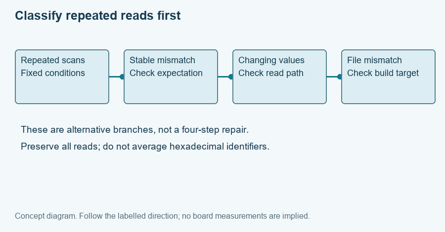
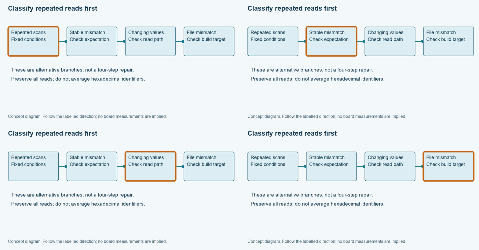
Show the diagram with each evidence item highlighted
The highlight moves between the same four items. It does not represent elapsed hardware time. Close this disclosure to hide motion; the static diagram contains the same information.
Enter the expected and read values as up to eight hexadecimal digits, with an optional 0x prefix. The tool normalizes their display and reports whether the complete values match. If they differ, it reports their XOR as a compact way to show which bit positions differ. XOR is a comparison aid, not an explanation of why those differences occurred.
Keep the expected-value source and chain direction with the comparison. A report without these fields cannot establish whether the right expectation was used. The worksheet flags missing context rather than filling it with guessed information. If the source defines revision bits that may legitimately differ, review those rules explicitly and record that separate interpretation; the tool does not silently decide which differences are acceptable.
Next compare the build target against the identified device. Use the release manifest and actual programming-file selection, not the filename alone. A filename can survive many rebuilds, copies and manual renames. If the device identity is stable and correct but the selected image targets another device, correct the image selection or build configuration and preserve the evidence that led to that decision.
Do not respond to a file mismatch by weakening device checks. Those checks help stop an image intended for one target from being applied to another. Resolve the source of the disagreement: a stale output directory, wrong project part, mistaken cable selection, incorrect assembly record or an obsolete fixture profile. Each calls for a different correction and a different regression check.
For a fixture, define acceptance in layers. The cable must identify the intended board position; the scan must return a documented device identity; the image manifest must match the intended assembly; and a runtime check must establish the application release. The fixture design article provides the broader record structure. Passing one layer does not automatically pass the others.
Without JavaScript, retain both raw values in a text record and compare them against the documented table. If you calculate an XOR manually, keep the original values beside it so a transcription error is visible. Preserve all repeated reads rather than only the read that matches expectations. A reviewer needs to know whether the result is stable, not simply whether a match occurred once.
Close the investigation with a bounded statement. “The expected and read values matched on these attempts at this chain position” is supported by a record. “The FPGA is genuine and all grades are correct” is not supported by IDCODE alone. If assistance is needed, share the exported comparison through the engineering entry together with the marking, board revision, source table and complete error. That package makes the unresolved identity question explicit.
Enable JavaScript for the local worksheet, or use the manual record procedure in the article. No data is submitted automatically.
Use the record for the next engineering decision
Review and download the worksheet above. For board-level help, open the engineering scope entry and include the exact board revision, observed failure and unresolved check. For an exact-part enquiry, use the component quotation entry with the complete ordering code and quantity. Opening either entry does not submit a request.
Reference scope
Prepared for the specific diagnostic task shown above. Source checks: 2026-11-14. UG470 references use v1.17; cited UG908 task pages were checked as 2026.1 where stated. Hardware commands and board behavior require verification in the actual setup. Concept figures and hypothetical examples are not measured test results.