
Tutorials
JTAG Works Only at Low TCK: How to Investigate
Published · Updated
If the same JTAG setup works at a lower TCK setting and fails at a higher one, you have a useful comparison. Preserve it before replacing parts. The comparison says that the outcome depends on the tested condition; it does not yet identify a cable defect, a board defect or a universally safe operating frequency.
This procedure turns an occasional successful connection into a repeatable frequency trial. It records attempts and failures at each setting while retaining cable, power and temperature conditions. The worksheet calculates observed failure fractions only. It deliberately does not recommend a maximum frequency from a small set of trials.
Open the diagnostic worksheet ↓
Define the operation that fails before sweeping TCK

Start by naming the operation: opening the target, identifying devices, programming a file, verifying configuration, or accessing a debug core. These operations should not be merged into one generic “JTAG pass.” A setup can enumerate a device and then fail during a later transfer. If the acceptance criterion changes between frequency settings, the resulting percentages are not a meaningful comparison.
Write a pass condition that can be applied consistently. For discovery, that might be a complete expected device list with recorded identifiers. For programming, it might include the tool’s completion result and a separate confirmation of configuration state. For a debug transaction, define the expected response. Keep downstream application behavior in its own field unless it is explicitly part of the test being compared.
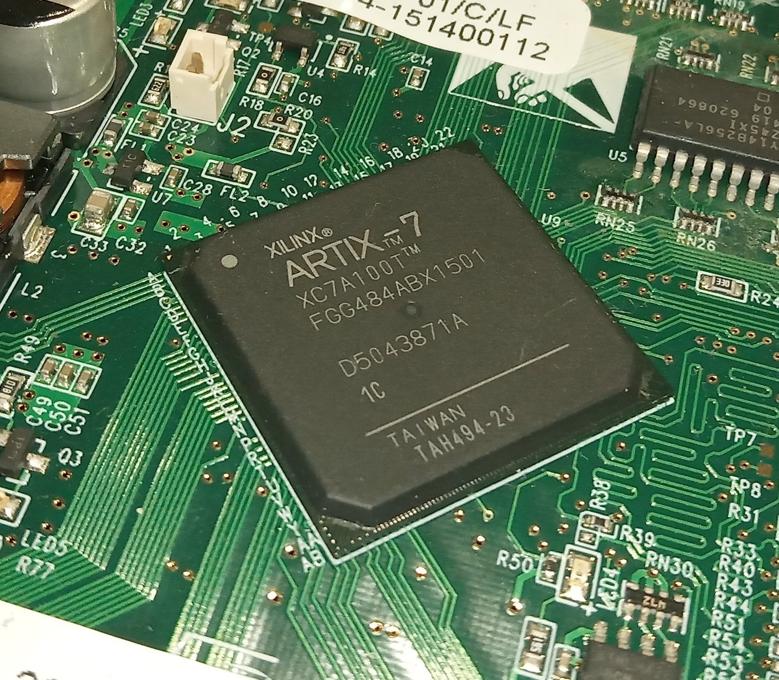
Identify the exact cable, adapters and target board. Photograph the arrangement before moving anything. The Artix-7 photograph here illustrates a device marking, not the cable arrangement used for your trial. Add your own board and cable images to the private test record so a later operator can reproduce connector orientation and extension routing.
Use the actual ordering code in the board record. The XC7A100T-1CSG324C device entry is a package-specific reference; it is different from the photographed FGG484 part. The chain may also contain other devices with their own requirements. Do not choose a TCK limit from the main FPGA alone while ignoring the rest of the scan path and programming hardware.
AMD’s lower-JTAG-frequency procedure, checked as UG908 2026.1, provides a supported way to change the target frequency. Use the settings available for your cable and software release. Its examples are not a measurement of your board’s margin, and a nominal setting should be recorded as selected rather than described as a measured clock frequency.
Choose a small set of supported settings that brackets the observed behavior. There is little value in sweeping dozens of values before confirming that the failure is repeatable. Keep the operation, file, power state and connection procedure constant. Record what resets between attempts: only the target session, the cable connection, the board power, or the entire workstation process. Those are different experiments.
If the failure is not actually repeatable, say so. A single low-speed success followed by a single high-speed failure does not isolate frequency from time, warm-up, contact movement or software state. Begin with repeated blocks at the two relevant settings and return to the original setting afterward. This establishes whether the apparent relationship survives a simple reversal.
Control the physical path and compare repeated blocks
Change one variable at a time. If a cable extension is removed while TCK is lowered, the next success cannot distinguish the two changes. First compare frequencies with the extension unchanged, then compare the extension under a fixed frequency if that operation is electrically appropriate. Name each setup so the trial log cannot accidentally combine results from different physical paths.
Keep the signal return path in view. Record cable type, length, adapters, connector seating and ground connections specified by the hardware documentation. Do not assume that a longer clock period compensates for every interconnect problem. Lowering the repetition rate does not necessarily make each signal transition slow. The programmer compatibility checklist is a useful prerequisite when cable reference voltage or target support is uncertain.
Avoid touching or rearranging the cable during a test block unless that is the variable under investigation. Mechanical movement can alter contact quality and routing. If movement occurs accidentally, mark the affected run rather than quietly including it in the original block. A record that retains such interruptions is more useful than a clean-looking table that hides them.
Use the board schematic to identify appropriate observation points if electrical measurements are needed. Record probe type, connection and loading concerns. A probe can change a marginal signal, especially when its ground connection introduces an additional path. A screenshot without the measurement setup is incomplete evidence. Do not infer a receiver’s timing margin from a waveform captured at an unrelated connector point.
Count every attempted operation according to the predefined rule. If the software must reconnect after a failure, record that recovery separately. Do not let an automatic retry convert a failed first attempt into an unqualified pass. The difference matters when a fixture must complete within a time budget or when a failure leaves the board in a state requiring operator intervention.
Use blocks that make drift visible. An example sequence is lower setting, higher setting, lower setting again, with the same number of attempts in each block. If the second lower-speed block also deteriorates, frequency alone is a weak explanation. Temperature, supply behavior, contact changes or session state deserve attention. This is experimental reasoning, not a claim that any particular one of those causes is present.
Record power and temperature conditions at the resolution actually available. A supply’s front-panel setting is not the same as a measured rail at the device. Room temperature is not a junction measurement. Label the quantities accurately so a reviewer knows what the experiment controlled and what it merely assumed. Use the board bring-up checklist when those distinctions are still unresolved.
An observed frequency relationship also does not validate the chain description. Wrong device ordering or undocumented IR lengths can coexist with a marginal connection. Retain the complete chain list and source-backed lengths in the setup record. AMD’s target troubleshooting guidance treats identification and instruction-length checks as explicit parts of the investigation.
Report observed failure rates without inventing a safe limit
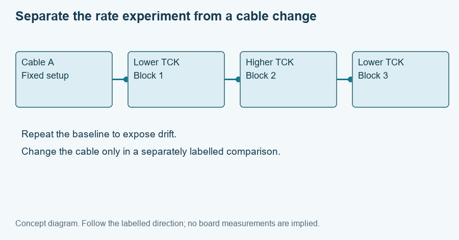
Show the diagram with each evidence item highlighted
The highlight moves between the same four items. It does not represent elapsed hardware time. Close this disclosure to hide motion; the static diagram contains the same information.

Enter each block as frequency in MHz, total attempts and failures. The worksheet rejects a zero attempt count, fractional counts, negative values and failures greater than attempts. It reports each block separately instead of silently pooling repeated frequencies. This preserves changes over time and allows you to see whether returning to the baseline reproduced the original result.
For a hypothetical illustration, twenty attempts with two failures gives an observed failure fraction of ten percent. Twenty attempts with no failures gives zero observed failures in those twenty attempts. It does not establish zero failure probability. These example counts describe arithmetic only and are not measurements from a board tested for this article.
Keep the denominator visible. “One failure” means something different in five attempts and five thousand attempts. Likewise, percentages rounded to a whole number can hide rare observed failures. The report includes counts alongside percentages so a reviewer can reconstruct the calculation. If your acceptance plan requires a statistical confidence statement, define the model and sampling plan separately; this worksheet does not supply one by implication.
Do not automatically choose the highest setting with no observed failures. The sample may be too small, the tested temperature range too narrow, or the cable arrangement different from production. A usable temporary debug setting and a qualified fixture setting have different evidence requirements. Write which decision the data supports and which remains open.
If a lower setting is adopted for bench work, record the exact setting, cable, board revision, operation and limitations. Keep the original high-speed failure record. Otherwise the temporary workaround may become an undocumented production assumption, and later operators may raise the speed without knowing why it was reduced.
For a fixture, define the permitted setup and regression test in the programming fixture documentation. Include recovery behavior, timeout handling and retention of failed attempts. A throughput improvement that increases manual recoveries can cost more production time than it saves, even when the nominal programming duration is shorter.
Without JavaScript, calculate failures divided by attempts and multiply by one hundred. Keep one row per block and retain the setup description above the table. Do not discard a block just because it conflicts with the initial hypothesis. A contradictory result is precisely the evidence that can prevent an incorrect frequency diagnosis.
The next experiment should answer one unresolved question. Examples include comparing the same cable without an extension, repeating at a controlled supply condition, or testing a documented reference board under the same operation. State the expected observations for competing explanations before running the experiment. This makes the result useful whether it supports or weakens your current suspicion.
For an engineering review, export the trial report with the complete error, chain identity and photographs of the physical path. Ask for help with the specific remaining decision: a reproducible debug setting, an interconnect investigation or a production acceptance plan. The failure counts are the start of that discussion, not a certificate that the interface has been qualified.
Enable JavaScript for the local worksheet, or use the manual record procedure in the article. No data is submitted automatically.
Use the record for the next engineering decision
Review and download the worksheet above. For board-level help, open the engineering scope entry and include the exact board revision, observed failure and unresolved check. For an exact-part enquiry, use the component quotation entry with the complete ordering code and quantity. Opening either entry does not submit a request.
Reference scope
Prepared for the specific diagnostic task shown above. Source checks: 2026-11-14. UG470 references use v1.17; cited UG908 task pages were checked as 2026.1 where stated. Hardware commands and board behavior require verification in the actual setup. Concept figures and hypothetical examples are not measured test results.