
Tutorials
JTAG Chain Order and IR Length: Debugging Multiple Devices
Published · Updated
In a multi-device JTAG chain, a correct FPGA identity does not establish that the chain description is correct. Another device’s instruction length, an optional link, or a reversed interpretation of scan order can invalidate the assumptions used to reach that FPGA. Start with the physical path, then compare the software representation. Do not begin by guessing an IR length for an unknown row.
This article builds a chain manifest that records each device, its documented instruction-register length and its source. The worksheet adds known lengths and marks unresolved entries. The sum is useful bookkeeping, but it cannot certify electrical continuity or prove that devices appear in the right order.
Open the diagnostic worksheet ↓
Trace the actual path from programmer TDI to TDO

Write the direction at the top of the drawing: programmer TDI, through each device, returning to programmer TDO. This convention matters more than whether you call the first device zero or one. A chain list copied between teams can appear reversed simply because one list is ordered by physical path while another follows a tool’s scan-display convention. Label both conventions instead of silently reversing one until the names look familiar.
Use the schematic for the exact assembly revision and annotate the populated state. Include optional resistors, jumpers, board-to-board connectors, buffers and devices that are bypassed by assembly options. A schematic net that exists in the design may not exist on the assembled variant. A continuity-oriented drawing should describe the board on the bench, including any fitted rework wires or temporary adapters.
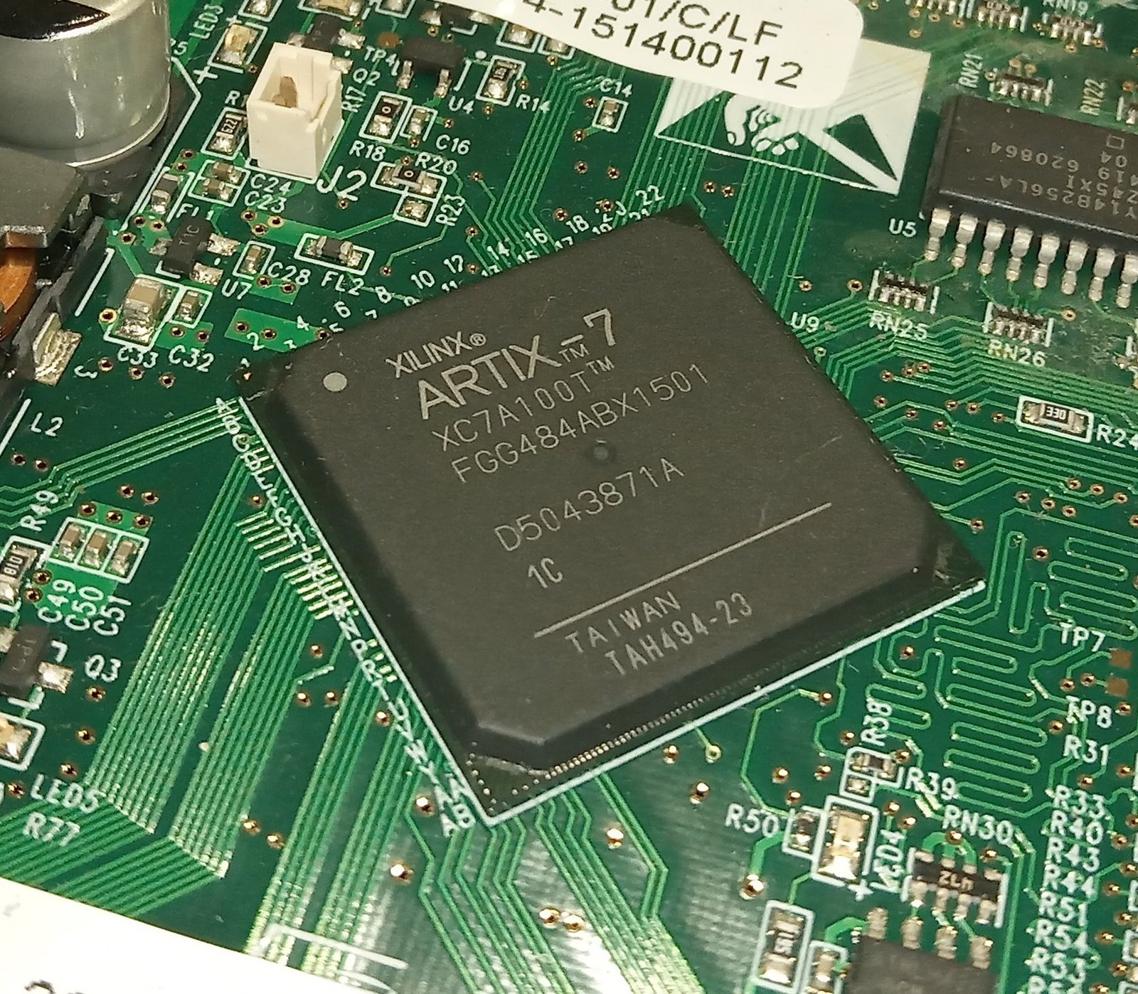
The Artix-7 photo provides an example of a device marking to record, not a claimed multi-device topology for the photographed board. Its neighboring components must not be assumed to belong to a JTAG chain merely because they are nearby. Topology comes from the schematic and observed wiring. Physical proximity is not an electrical connection.
Assign a reference designator and exact device identity to every manifest row. Include non-FPGA devices when they are in the scan path. If the identity is unresolved, write that explicitly and preserve the observed marking. Do not replace an unknown component with a generic “FPGA” label because the programming task only concerns the main FPGA. The intervening device can still affect the scan operation.
Record power and isolation conditions alongside topology. A device may be physically present but unpowered in the current test mode. A buffer may require an enable state that differs between board revisions. Verify these conditions using the board documentation rather than treating the chain as a passive wire. The PCB bring-up checklist helps keep those board conditions separate from software settings.
Check the connector’s view direction as well. A mating-face drawing, top-side board view and cable-side view can all be correct while looking mirrored. Use pin-one identification and named signals from the actual connector drawing. The programmer compatibility checklist covers the broader cable/target requirements; it is especially useful before introducing an adapter into a previously working chain.
For an Artix-7 assembly, retain the full ordering code even if a tool uses a shorter name. The XC7A100T-1CSG324C page is one package-specific catalogue entry, not a substitute for every XC7A100T package. The photograph uses FGG484. Keep this package distinction in the assembly record while using the correct device-level scan documentation for the relevant part.
Reconcile scan order and documented instruction lengths
Capture the tool’s complete device list before editing its interpretation. Save the displayed order, device names, raw identifiers where available and any unknown entries. Then map each row to a reference designator in the physical drawing. If the convention is unclear, consult the tool documentation or perform a documented identification procedure rather than assuming that top-to-bottom order equals TDI-to-TDO order.
Instruction-register length and data-register length are different quantities. A familiar identification-register width does not tell you the instruction length. Likewise, the short bypass data path does not imply that the instruction register is one bit long. The manifest asks specifically for IR bits so these concepts do not become an ambiguous “JTAG length” field.
Find each IR length in the manufacturer’s device documentation or applicable BSDL file. Record the file name, revision and device/package scope where supplied. For 7 series devices, UG470 v1.17 Table 1-1 includes device-specific instruction lengths. Do not generalize a value from one family member to every device in a mixed chain.
AMD’s target troubleshooting guidance, checked as UG908 2026.1, notes that automatic IR-length determination can need correction for unknown devices. The important action is to check against a source. A manually entered number that makes an error disappear remains unverified unless the device documentation supports it.
Keep unknowns visible. If a three-device chain has two documented lengths and one unresolved length, report the known subtotal and the unresolved position. Do not call the subtotal the complete chain length. This sounds obvious, but spreadsheets often turn a blank cell into zero and produce a convincing total. The worksheet below refuses to treat a missing or invalid length as documented evidence.
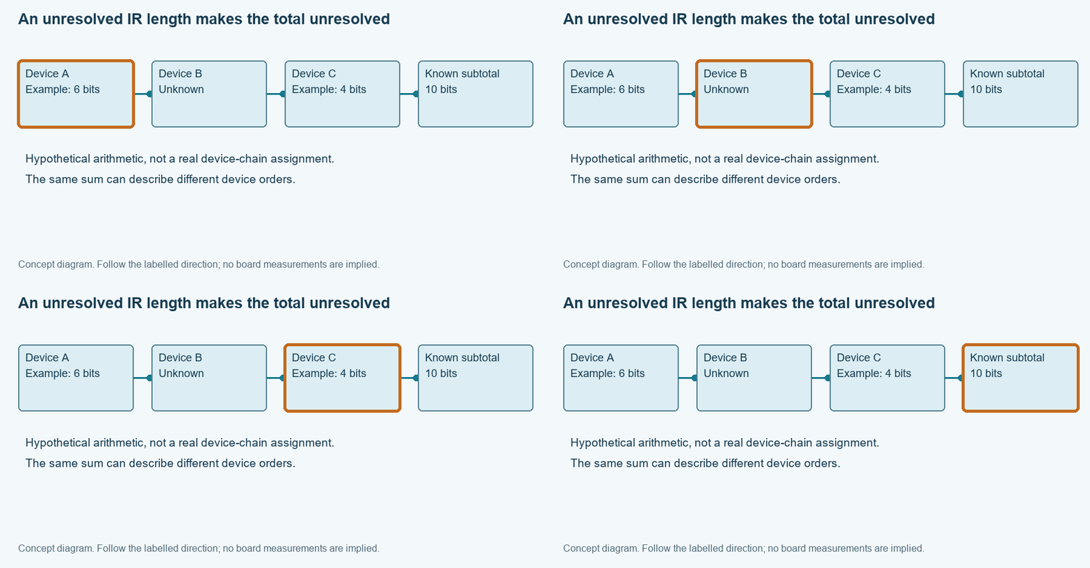
Use a conceptual example to test your record format: device A has a documented six-bit IR, device B has an unresolved IR, and device C has a documented four-bit IR. The known subtotal is ten bits; the total remains unknown. Once B’s source establishes eight bits, the documented total becomes eighteen. These are hypothetical lengths for illustrating the arithmetic, not values to copy into a real mixed-device chain.
An eighteen-bit total still does not establish the order. Six plus eight plus four gives the same sum in every permutation. Nor does it prove that the tool selected the intended instruction in every device or that the return path is electrically sound. Treat the total as a consistency check within a larger manifest. It is useful precisely because its scope is narrow and inspectable.
If discovery changes with clock frequency, preserve that as a separate observation. Do not alter the topology record to compensate for unstable scans. First make the physical and documentary description internally consistent, then investigate repeatability under supported electrical and frequency conditions. A correct manifest cannot repair a marginal connection, and a slower successful scan cannot validate an undocumented IR assumption.
Retain the source files themselves where your document-control process permits. A link can move or a vendor download can be revised. A file hash and revision label make the manifest reproducible later. They also let a reviewer determine whether two operators used the same instruction-length source when their chain profiles differ, without relying on recollection.
Maintain a chain manifest through board and fixture changes
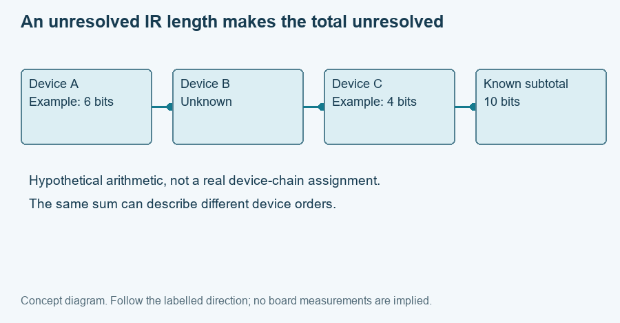
Show the diagram with each evidence item highlighted
The highlight moves between the same four items. It does not represent elapsed hardware time. Close this disclosure to hide motion; the static diagram contains the same information.
Enter one line per device in physical TDI-to-TDO order. Use the format device, vertical bar, IR bits, vertical bar, source. Include the reference designator in the device name. The worksheet produces a numbered list, a sum of known lengths and a warning when source or length information is missing. It preserves your stated display-order convention and jumper conditions in the exported record.
The manifest is most useful when it belongs to a board revision. After a design or assembly change, compare the old and new physical paths before reusing an old fixture profile. A removed device, moved connector or changed bypass option can invalidate a profile even if the main FPGA part number remains unchanged. Review the actual differences instead of approving the new board solely because its filename resembles the old one.
For each change, record the affected reference designator, previous connection, new connection and supporting schematic revision. Then capture a fresh scan under the documented power state. Keep the old capture as historical evidence rather than overwriting it. If a new scan disagrees with the revised manifest, the difference becomes visible without reconstructing the previous setup from memory.
Build a fixture acceptance procedure that distinguishes documentation checks from physical tests. The manifest review establishes intended identities, lengths and order. The connection test establishes the observed chain under stated conditions. Programming and runtime checks establish later behavior. The programming fixture guide shows how to preserve those stages as separate results instead of one opaque green indicator.
A practical regression sequence starts with the unchanged reference board, then tests the revised board using the revised profile, then returns to the reference setup if needed. This helps reveal a cable or workstation change that occurred during the same session. Do not claim a board-change cause if the supporting setup changed at the same time and no comparison was retained.
Without JavaScript, the manifest works as a plain table. Sum only documented positive IR lengths, mark missing sources and retain the direction statement above the table. Another reviewer should be able to reproduce the arithmetic and trace every length to its source. The worksheet does not add hidden knowledge; it makes these bookkeeping checks harder to overlook.
For an engineering review, export the manifest and attach the chain portion of the schematic with the assembly options marked. Include the complete scan list and the unresolved question: direction mapping, unknown-device identity, instruction length or a condition-sensitive physical path. That is enough to begin a focused investigation without inventing a topology from a cropped screenshot.
Enable JavaScript for the local worksheet, or use the manual record procedure in the article. No data is submitted automatically.
Use the record for the next engineering decision
Review and download the worksheet above. For board-level help, open the engineering scope entry and include the exact board revision, observed failure and unresolved check. For an exact-part enquiry, use the component quotation entry with the complete ordering code and quantity. Opening either entry does not submit a request.
Reference scope
Prepared for the specific diagnostic task shown above. Source checks: 2026-11-14. UG470 references use v1.17; cited UG908 task pages were checked as 2026.1 where stated. Hardware commands and board behavior require verification in the actual setup. Concept figures and hypothetical examples are not measured test results.