
Tutorials
FPGA Programming Succeeds but the Design Does Not Run
Published · Updated
Programming success proves a limited part of the system. It does not prove that the user clock is present, the application reset has released, the expected image is running or the output reaches the correct package pin. When the tool reports success but the board appears inactive, stop repeating the same download and define the first application event that should be observable.
This guide starts after configuration has been established. It builds a short evidence chain from image identity through clock and reset to a first output. The checklist at the end records which links have been observed and which remain assumptions. It is designed to produce a minimum reproducible test, not a generic list of every possible FPGA fault.
Open the diagnostic worksheet ↓
Define the first output and the image that should produce it

Write the expected result before opening another debug window. “The design does not run” is too broad. A better statement names an output, an event and a condition: a heartbeat should toggle after reset release, a status register should return a build identifier, or a ready signal should assert after a defined initialization exchange. Include the permitted observation window and the equipment used to detect the event.
Separate “not observed” from “observed absent.” An LED that appears dark may be connected with an unexpected polarity or may toggle too quickly to judge visually. A software read may use the wrong address or a cached response. The absence of your expected indication is a starting symptom; it is not yet proof that every internal register is static.
Record the exact programming file and release identity. A recently modified source file does not establish that the selected bitstream contains that modification. Build directories, copied outputs and fixture packages can lag behind the source tree. Preserve the file path and manifest, then seek a fresh runtime identifier if the design provides one. Do not let a familiar filename stand in for that evidence.
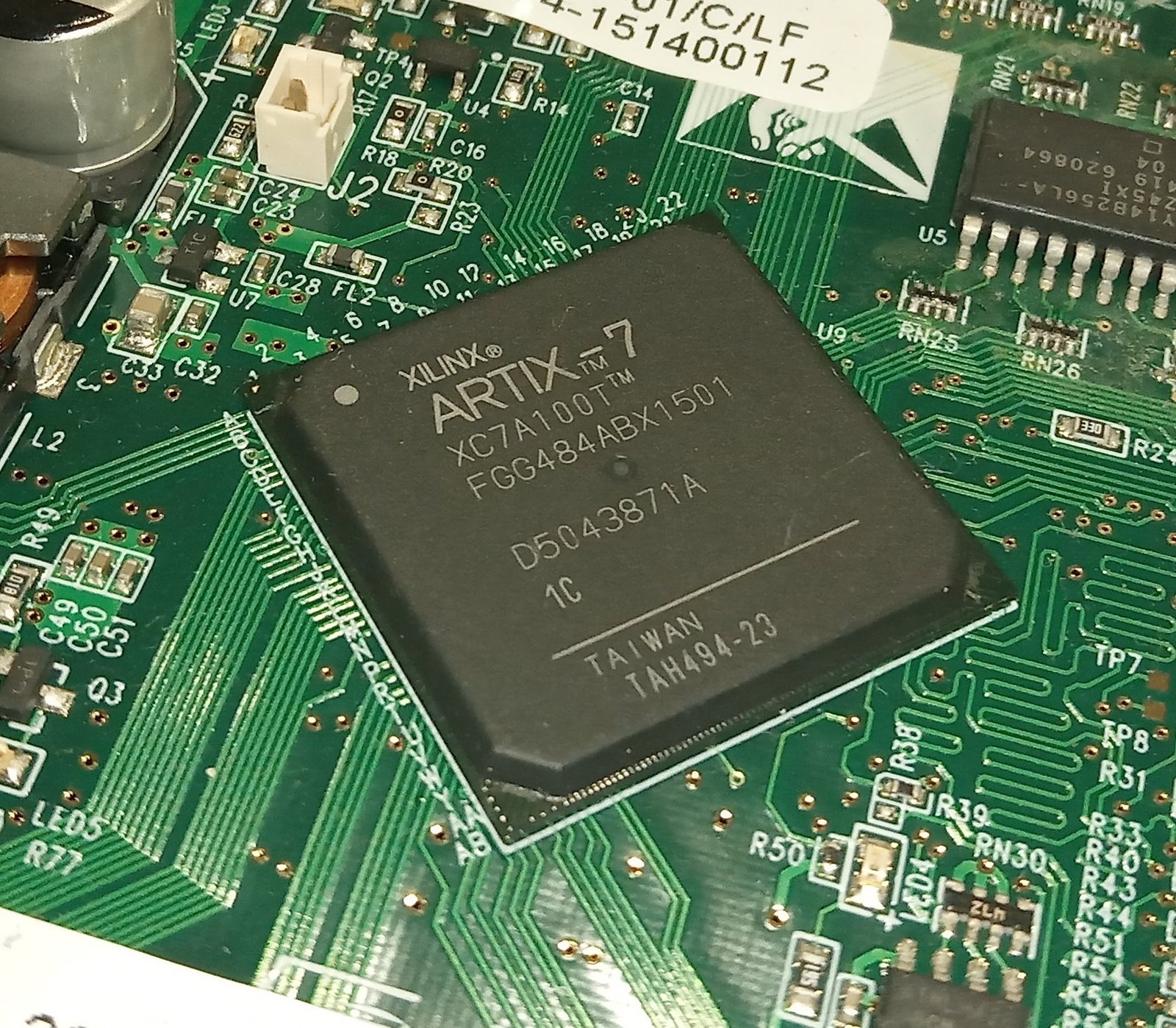
The board identity must be equally specific. The Artix-7 photograph shows a package marking, not an output pin map for your board. The XC7A100T-1CSG324C catalogue page describes a different package from the photographed FGG484 part. Use the actual package and board revision when tracing constraints. A correct logical port name connected to the wrong package pin can produce a completely silent external test.
Retain the configuration result separately from the application result. If configuration has not actually been confirmed, return to that investigation first. If JTAG programming succeeds but independent boot fails, the Artix-7 flash-boot workflow addresses the persistent boot path. This article assumes the immediate problem is application behavior after a demonstrated configuration event.
Choose the smallest useful witness. A simple counter output in the relevant domain can show that part of the clock/reset/logic path is active. It cannot prove a whole data pipeline or another clock domain. State exactly what the witness establishes. A heartbeat generated by an unrelated always-running clock is a poor test of a stalled acquisition domain, even if it makes an LED blink reassuringly.
Keep the expected and actual result side by side in the record. Include the first action that should trigger the event and any external dependencies, such as a host command, peripheral ready signal or reference clock. A design that waits intentionally for an absent handshake is different from a design whose clock is missing. The test must distinguish those cases.
Trace clock, reset and constraints through one domain
Begin with the domain that produces the first expected output. Identify its clock source, any clock-management stage, reset source and relevant enable conditions. Draw this path from the board input to the witness register and output. Avoid expanding immediately into every domain in the design; the purpose is to locate the first unproven dependency.
Observe the clock at a point that answers the question. A board oscillator output does not prove that the intended clock reaches the implemented logic. Conversely, an internal debug core may depend on a clock that is itself missing. If a debug view is unresponsive, include the observer’s dependencies in the investigation rather than assuming the target logic is the only thing that can fail.
Check reset polarity, assertion conditions and release in that same domain. A schematic signal named RESET and an RTL port named reset_n can be connected incorrectly even when both names seem familiar. Trace the implemented logic and actual board signal rather than relying on suffix conventions. For release timing and synchronization, follow the design’s documented clock-domain strategy and verify the relevant behavior in simulation and implementation.
Distinguish a reset held active from an enable that prevents state changes. Both can leave a counter or state machine motionless. Observe or expose the necessary control conditions so the test can tell them apart. Do not remove reset or force enables globally as a first experiment; that can hide the intended startup dependency and create new behavior that is difficult to interpret.
Next trace the first output through constraints. Match the RTL top-level port, constraint entry, package pin, schematic net, connector or component and measurement point. Check I/O standard and bank-supply compatibility against the actual board requirements. The PCB bring-up checklist is useful for keeping those board-level facts visible during a logic investigation.
Inspect the implemented design and relevant reports, not only the text of an old constraint file. A file may be excluded, a top-level name may have changed or a build may use another constraint set. Record which build produced the programming file. A report from an earlier implementation does not establish the constraints in the image currently selected for programming.
For a conceptual heartbeat, a free-running binary counter’s bit k toggles at half the rate of bit k minus one, and has a full-cycle frequency of clock frequency divided by two to the power k plus one. This arithmetic helps choose an observable rate, but it assumes the counter is actually clocked and not held or gated. It is a calculated design example, not a measured board result.
Use simulation to test the expected sequence before treating a missing external event as a board defect. Exercise reset, enable and handshake conditions with explicit stimulus. Then compare the simulated assumption with the actual external condition. If the simulation drives a ready input high from time zero while the board never asserts it, the mismatch is in the test assumptions before it is in the FPGA hardware.
When a programming cable or debug connection seems involved, retain its identity and supported setup. The programmer compatibility article supplies that context. However, once configuration is established, repeatedly swapping cables is unlikely to explain a stable pin-constraint error. Let the first missing application dependency determine the next experiment.
Reduce the design and preserve the evidence chain
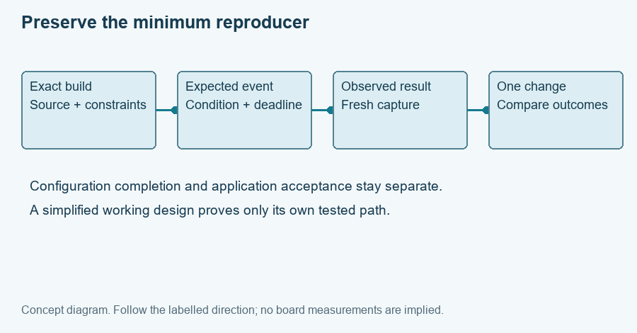
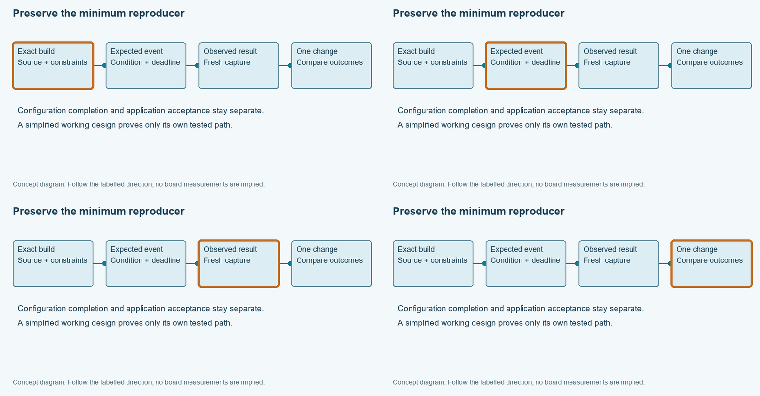
Show the diagram with each evidence item highlighted
The highlight moves between the same four items. It does not represent elapsed hardware time. Close this disclosure to hide motion; the static diagram contains the same information.
The checklist asks whether configuration completion, the relevant clock, reset release, a first output, constraints and runtime identity were observed. Select unknown when the evidence is absent. The output is a list of recorded and unresolved links. It does not score the design as safe or functional, and it does not treat a completed form as an acceptance test.
Build the minimum reproducer around one question. If the question is whether the board clock and output path work, retain only the required clock/reset path and a simple witness with exact constraints. If the question is a peripheral handshake, retain the smallest transaction that exposes that handshake. Removing unrelated features makes the observation easier to interpret, but preserve the original failing build for comparison.
Change one dependency at a time and state the expected difference. For example, exposing the internal reset state can distinguish a held reset from a running state machine with a wrong external pin. A successful simplified design then establishes its own path; it does not prove that the original larger design was correct. Record the difference between the two designs so the simplification remains a diagnostic experiment.
Keep the observer honest. An ILA trace, software register read or external scope capture has its own clocking, triggering and freshness conditions. Record those conditions with the result. If a capture shows no transition, check whether the acquisition window included the expected event and whether the trigger could ever fire under the failing condition.
A useful reproduction package contains the board revision, exact part, build manifest, relevant source and constraints, expected first event, observed result and the controlled change being tested. Add the smallest supporting waveform or log. Avoid attaching a large project archive with no explanation of which output should demonstrate the problem; volume does not replace a defined test.
For repeated production work, use the fixture design guide to separate programming acceptance from application acceptance. The fixture should record both results and their criteria. A green programming status must not automatically mark a board’s clock, reset and external interfaces as tested when the fixture never observed them.
Without JavaScript, reproduce the checklist in a table with columns for expected behavior, evidence, result and next check. A blank evidence cell remains unresolved even if the result column says pass. This manual version has the same purpose as the interactive tool: it keeps a plausible explanation from becoming an unsupported conclusion.
For an engineering discussion, export the checklist and identify the first missing application event. Include the minimum reproducer and the difference from the original design. A reviewer can then follow the same clock/reset/output path instead of trying to infer the entire system from “programming completed successfully.”
Enable JavaScript for the local worksheet, or use the manual record procedure in the article. No data is submitted automatically.
Use the record for the next engineering decision
Review and download the worksheet above. For board-level help, open the engineering scope entry and include the exact board revision, observed failure and unresolved check. For an exact-part enquiry, use the component quotation entry with the complete ordering code and quantity. Opening either entry does not submit a request.
Reference scope
Prepared for the specific diagnostic task shown above. Source checks: 2026-11-14. UG470 references use v1.17; cited UG908 task pages were checked as 2026.1 where stated. Hardware commands and board behavior require verification in the actual setup. Concept figures and hypothetical examples are not measured test results.