
Tutorials
Can an Artix-7 Input Accept 5 V? Build a Level-Shifting Check
Published · Updated
A logic-high threshold does not establish voltage tolerance
Do not connect a 5 V push-pull output directly to an Artix-7 input on the assumption that anything above VIH is acceptable. VIH is a recognition threshold. The permitted input-voltage range and absolute maximum ratings answer different questions. Read the relevant entries and notes in DS181 for the actual bank and operating condition.


Identify the source output type first. A push-pull output drives both states; an open-drain output relies on a pull-up. The pull-up rail determines the high level of an open-drain net. A connector marked “5 V” may describe power rather than signal levels, so inspect its schematic instead of inferring the interface from its label.
Board bring-up sequence: Use the board bring-up sequence to test the translator power states in order.
I/O count and allocation: Keep translator direction and occupied pins in the I/O allocation.
Choose the translation architecture from direction and timing
For a unidirectional signal, a suitably specified buffer or translator can separate the two voltage domains. Check both supply ranges, input tolerance, output levels and propagation delay. For a bidirectional interface, direction control and turnaround matter. An automatic-direction device is not interchangeable with a direction-controlled transceiver simply because both packages have two supply pins.
A resistor divider is a limited unidirectional technique, not a general replacement for a bus translator. Receiver capacitance and resistor values affect edge shape, and a divider does not provide a controlled drive path in the reverse direction. A series resistor by itself does not turn an unspecified input into a 5 V tolerant input. Do not size one from a guessed clamp-current limit.
External input/output timing: Add translator propagation delay to the external timing model.
Clock-domain synchronization: A translated asynchronous signal can still require synchronization.
Test the powered and unpowered combinations
List four conditions: both sides powered, source only, FPGA side only and neither side powered. For each, identify whether an output can drive the net, whether the translator isolates it, and which data-sheet condition supports that behavior. Include output-enable default state and power sequence.
The check below records missing evidence rather than issuing a blanket compatibility verdict. Close the record with exact part numbers and supply conditions. After the electrical path is established, include translator delay and board delay in the timing budget. Seeing correct data at a low test frequency does not establish the voltage or timing margin of the finished interface.
Power-on test record: Record source-only and receiver-only tests in the power-on plan.
Use the equations and review steps above. Interactive checks require JavaScript.Watch the short translation needs a direction sequence
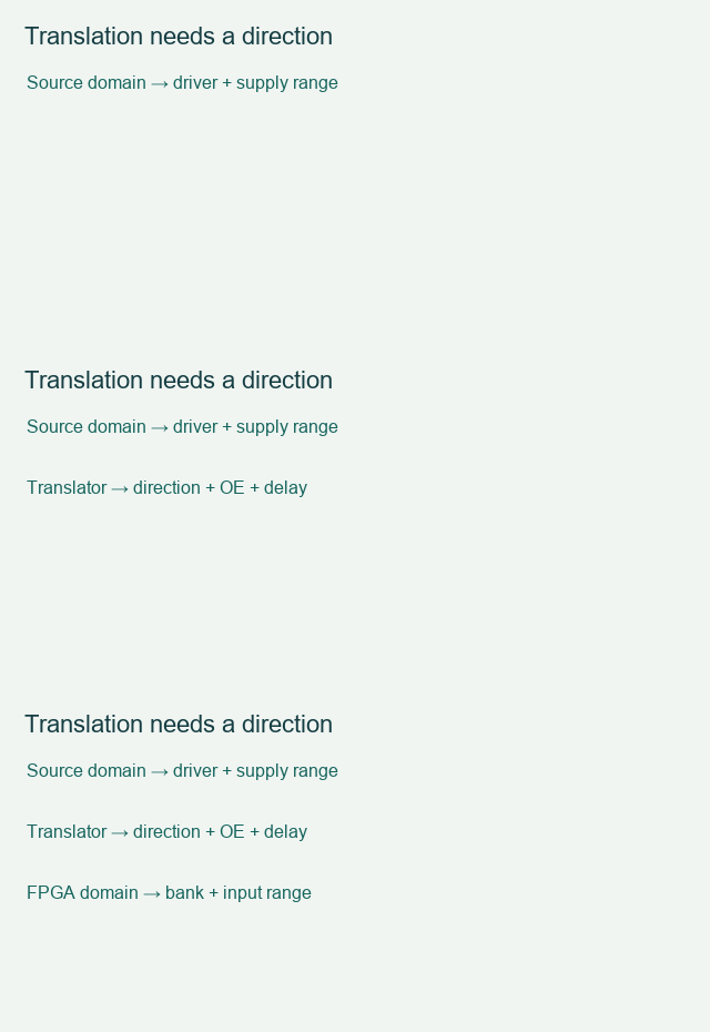
Save the check result with your exact device, board revision and unresolved conditions. Discuss the interface requirements when the remaining issue needs a board or implementation review. Opening this link does not submit the worksheet.
Sources and example scope
Documentation checked 17 November 2026. Worked values are illustrative calculations. No board measurement or Vivado implementation run is claimed. The worksheet checks entered assumptions and does not inspect your schematic or project files.
Back to Tutorials