
Tutorials
Reading the Artix-7 Configuration Status Register
Published · Updated
Keep the raw register value before decoding it. A configuration status screenshot without the register name, device family and capture time is easy to misread. Artix-7 STAT, a JTAG instruction-register status field and a boot-history register are different records. A decoder for another FPGA generation can produce convincing labels for the wrong bits.
The reader below is intentionally restricted to Artix-7 STAT using UG470 v1.17. It extracts named fields, preserves reserved bits and decodes the startup-state encoding. It does not contact hardware or infer a root cause from a single word. Use it to make a recorded observation easier to review.
Open the diagnostic worksheet ↓
Confirm the family, register and capture event
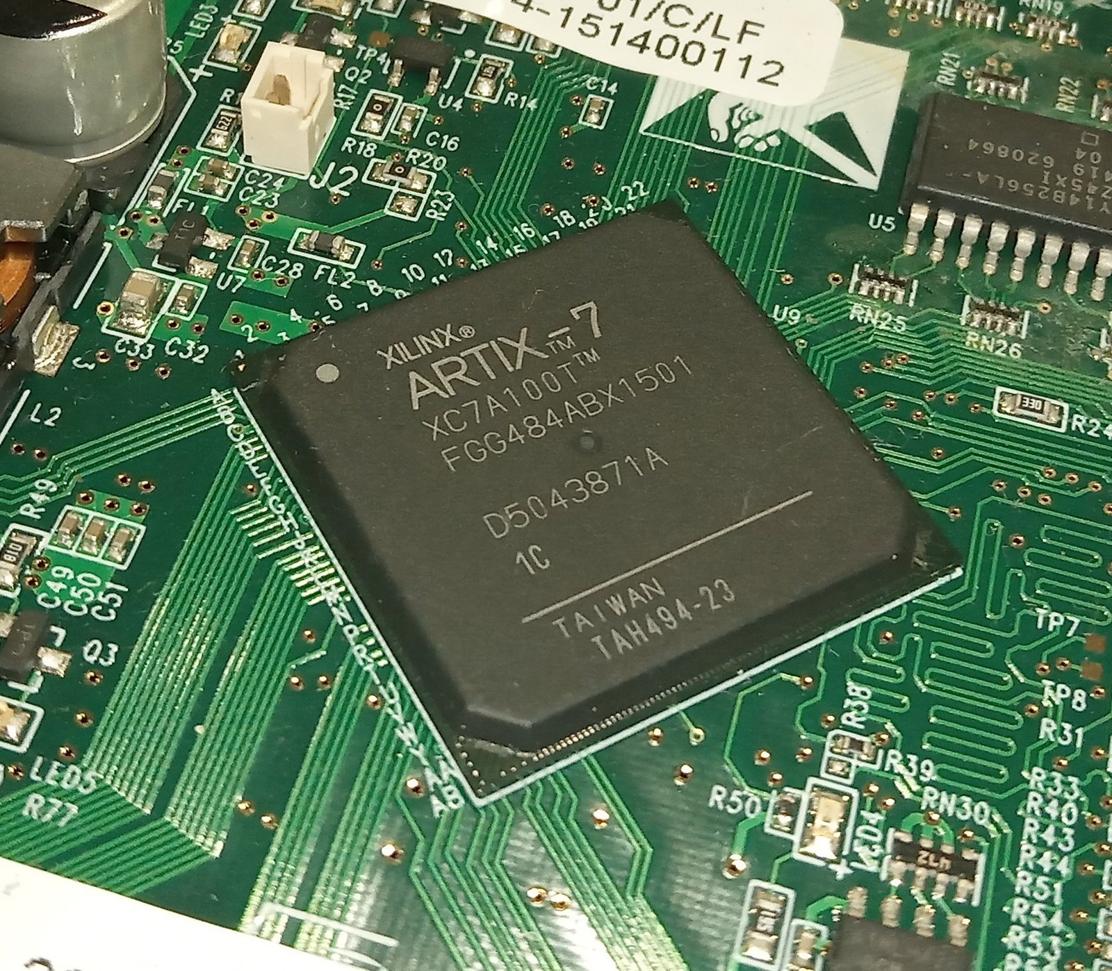

Identify the installed FPGA and board revision first. The real photograph shows an XC7A100T in an FGG484 package. The site’s XC7A100T-1CSG324C entry is another package-specific record, not the identity of the photographed part. Keep the actual ordering code in the capture manifest even though this decoder is restricted at the family level.
Record how the value was obtained. A tool’s named device property, a configuration-register read and a copied log line should retain their exact labels. Do not rename an arbitrary hexadecimal value “STAT” merely because it appears near a configuration message. If the acquisition method is unclear, resolve that before interpreting the bit positions.
Distinguish acquisition from interpretation. The worksheet only interprets the value you enter. It cannot confirm that a tool read the intended device, that the display was refreshed, or that the number belongs to the latest attempt. Include the cable/target identity and chain position when multiple devices are connected. A correct decoder applied to the wrong device record is still a wrong diagnosis.
Capture the value before an action that may change the state. Examples include reprogramming, restarting a sequence, changing a boot option or cycling power. Save the failing-state observation first, then record any later value as a separate event. A post-recovery status word cannot reconstruct every condition that existed at the original failure.
State whether the capture followed direct JTAG programming or independent boot. Those paths can leave the board at different points in the investigation. The Artix-7 flash-boot article helps establish which operation actually succeeded. Do not infer that a flash image is correct just because a status word was captured after a separate JTAG download.
Use the register table for the exact family. This worksheet references UG470 v1.17, Tables 5-28 and 5-29, pages 105–107. It rejects other-family and other-register selections. In particular, it is not a Virtex-5 or UltraScale decoder. Keeping that restriction explicit is more useful than supporting several families with an ambiguous automatic guess.
Record the raw word as hexadecimal with its radix stated. Leading zeros may be omitted on input, but the report restores an eight-digit representation. Do not copy a decimal value into a hex field without conversion. A plausible-looking result is not evidence that the radix was correct. Preserve the original log text beside the normalized value so transcription errors remain detectable.
Read fields without collapsing them into one verdict
The decoder extracts individual flags and multibit fields by position. Its essential distinction is between what a field reports and what caused that reported state. An error flag can narrow an investigation without identifying the failed physical component. A clear flag at one capture time also cannot establish that no transient problem occurred earlier.
The implemented field map is CRC_ERROR at bit 0; PART_SECURED at 1; MMCM_LOCK at 2; DCI_MATCH at 3; EOS at 4; GTS_CFG_B at 5; GWE at 6; GHIGH_B at 7; MODE at 10:8; INIT_COMPLETE at 11; INIT_B at 12; RELEASE_DONE at 13; DONE at 14; ID_ERROR at 15; DEC_ERROR at 16; XADC_OVER_TEMP at 17; STARTUP_STATE at 20:18; and BUS_WIDTH at 26:25. Reserved ranges are retained without interpretation.
STARTUP_STATE requires particular care. Its encoded three-bit value is not a simple binary phase number. The worksheet applies the table’s mapping and prints both the raw field and decoded phase. For example, raw field 4 corresponds to phase 7, rather than phase 4. Keeping both representations in the output makes the conversion auditable and avoids a misleading diagnosis caused by ordinary integer formatting.
Keep pin-related observations and internal release/status observations separate. DONE and RELEASE_DONE are not interchangeable labels, and INIT_B and INIT_COMPLETE likewise represent different evidence. If two related fields differ, that difference is a reason to consult the relevant signal path and phase. Do not “correct” one field to match the other because a simplified diagram shows them together.
Treat reserved bits conservatively. The worksheet prints their raw masked value but assigns no meaning. A nonzero reserved bit should not be relabeled as a newly discovered fault flag. Preserve the value, verify the register/family/version and consult the authoritative source or vendor support if the observation remains unexplained. Guessing names for undocumented bits makes the report harder to trust.
A useful manual check is a one-bit test of the decoder, not a claim about real hardware. Entering a hypothetical word with only bit 14 set should show DONE as one while unrelated single-bit fields remain zero. A word constructed to test a field can be electrically implausible as a complete device state; it is still useful for checking extraction logic. Label such inputs as test vectors, never as captured board results.
Do not use the status word as a substitute for a timed capture when timing is the question. One read cannot show the duration of a state, the order of earlier transitions or every event between reads. If a startup issue is intermittent, correlate the register record with external observations and the operation log. The PCB bring-up checklist provides the wider measurement context.
Also avoid assuming that a status field validates the entire application. A completed configuration-related stage does not establish correct pin constraints, user reset behavior, application clocks or data integrity. Define an application observation separately. Register interpretation is strongest when it answers a narrow question and leaves the remaining questions visible.
When copying a value from a screenshot, have the transcription checked against the original before drawing conclusions. Confusing one hexadecimal character can alter several interpreted fields. Prefer copied text when available, but retain the screenshot if it establishes the selected device and capture context that the text alone does not contain.
Save raw and decoded evidence together

Show the diagram with each evidence item highlighted
The highlight moves between the same four items. It does not represent elapsed hardware time. Close this disclosure to hide motion; the static diagram contains the same information.

Select Artix-7 and STAT, enter the raw value, and add the capture phase and timestamp. The report includes the normalized word, field values, decoded startup phase and reserved-bit mask. It retains your original context fields so the result can be reviewed without reopening this page. An empty or malformed value is rejected rather than treated as zero.
Keep the raw acquisition record next to the exported report. The original tool log establishes where the number came from; the report explains how this particular decoder interpreted it. If the decoder or source table changes later, the raw record allows a fresh interpretation. Saving only a verbal diagnosis such as “startup incomplete” loses information that may be important to the next reviewer.
For repeated attempts, use one capture record per event. Include the board, image identity, power-cycle procedure, exact capture action and any change since the previous attempt. Do not overwrite a failed-state word with the next successful word. The comparison between the two is often the most valuable part of the investigation.
When two words differ, identify the changed fields and ask whether the capture phases were comparable. A difference after a different programming path or capture delay may be expected. Conversely, identical words do not prove that the complete physical behavior was identical. The register is one observation channel with a defined scope, not a complete recording of the board.
A hypothetical review illustrates the boundary. Suppose a report has a raw word and a decoded startup phase, but no timestamp or acquisition method. The next action is to recover capture context, not to recommend changing configuration settings. Suppose instead that a successful/failed pair has matched capture conditions and a reproducible field difference. That supports a targeted follow-up measurement, while the physical cause still requires evidence.
The programming fixture guide is useful when status capture becomes part of a repeated test. Define when the fixture reads, which register it reads and how the raw word is retained. Store the decoder revision with the derived result. This prevents a future software update from making old and new status reports look comparable when their interpretation rules differ.
Without JavaScript, use the same source table and extract fields from the raw word with a calculator that supports bit operations. Keep the family, register and source version at the top of the record. Check multibit encodings explicitly instead of assuming their numeric value is the human-readable meaning. Reserved ranges should remain reserved in the manual record too.
For an engineering review, provide the exported report, original acquisition text and the expected-versus-observed startup event. A request framed around a reproducible field difference is more useful than a screenshot asking whether the whole word is “good.” The intended result is a traceable next experiment, not a universal pass/fail status constant.
Enable JavaScript for the local worksheet, or use the manual record procedure in the article. No data is submitted automatically.
Use the record for the next engineering decision
Review and download the worksheet above. For board-level help, open the engineering scope entry and include the exact board revision, observed failure and unresolved check. For an exact-part enquiry, use the component quotation entry with the complete ordering code and quantity. Opening either entry does not submit a request.
Reference scope
Prepared for the specific diagnostic task shown above. Source checks: 2026-11-14. UG470 references use v1.17; cited UG908 task pages were checked as 2026.1 where stated. Hardware commands and board behavior require verification in the actual setup. Concept figures and hypothetical examples are not measured test results.