
Tutorials
Reading Artix-7 INIT_B and DONE During Configuration
Published · Updated
INIT_B and DONE are useful configuration observations only when their timing is known. The same low level can mean different things during initialization and after loading has begun. Start with when the level occurred, where it was measured and what the board was doing. Two static bits cannot identify every configuration failure.
This article focuses on Artix-7 signal observation and interpretation. It does not replace the complete flash-boot procedure. Use the worksheet to preserve phase, pin levels and measurement context, then choose the next observation. Its output is a diagnostic direction, not an automatic component-failure verdict.
Open the diagnostic worksheet ↓
Locate the signals and establish the observation conditions
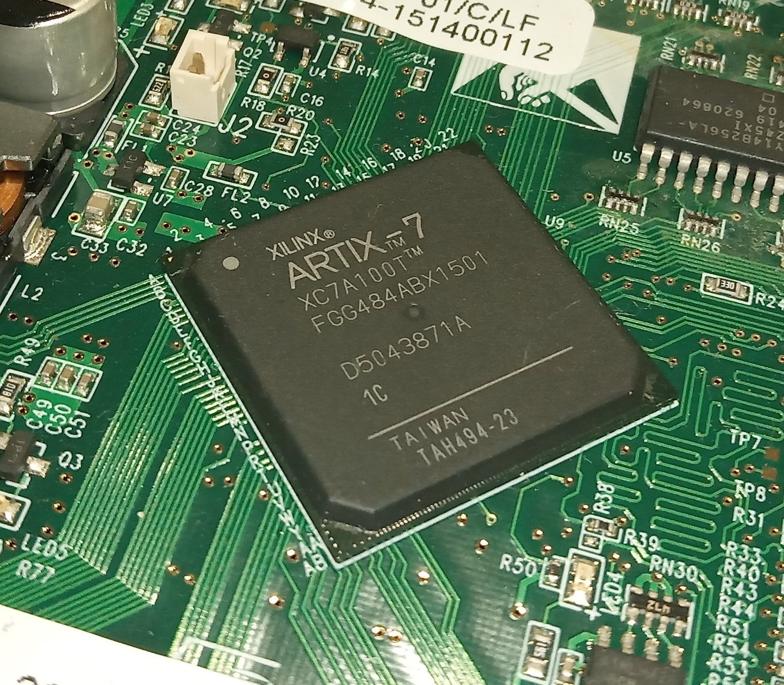

Use the schematic for the actual board revision to locate INIT_B and DONE. Follow each signal through pull-ups, LEDs, buffers, test points and other connected devices. A label on a connector can refer to a buffered or combined signal rather than the FPGA pin itself. Record exactly where the probe or meter connects and what electrical path lies between that point and the FPGA.
The Artix-7 package photograph is an identity reference only. It does not expose the ball assignments or establish accessible test points. Do not copy pin positions from a different package. The XC7A100T-1CSG324C catalogue entry and the photographed FGG484 device are different package variants. The correct package pinout and board schematic must agree before a measurement point is chosen.
Identify the pull-up supply and all devices capable of affecting the net. A signal released internally can still be held low elsewhere. Conversely, a high level at a buffered indicator does not automatically establish the voltage at the FPGA pin. Keep internal release state and external pin observation as separate evidence. This distinction becomes especially important when multiple devices share configuration-related signals.
Check the permitted voltage and probe connection against the board and device documentation. Avoid choosing a pull-up value or voltage from an unrelated development board. The PCB bring-up checklist is the broader starting point when rail identity, power sequencing or test access remains uncertain. A configuration interpretation built on an unverified measurement connection is fragile even when the logic sounds correct.
Choose an instrument that can observe the event of interest. A meter can establish a stable level but can miss a brief transition. A scope capture can show timing, provided the trigger, sample setup and probe arrangement are recorded. An LED gives a convenient indication of its own circuit but is not a substitute for a time-correlated capture when an intermittent event is suspected.
Define the time origin. It might be application of power, release of a documented reset, or initiation of a programming operation. Use the same origin when comparing successful and failed attempts. A statement such as “DONE is low after two seconds” is incomplete unless the event starting those two seconds is clear and the expected sequence is defined for that board.
Retain the first capture before changing straps, images or power settings. The initial failing sequence is often the only record of the original condition. Annotate the image with the board revision, measurement points and capture time in your lab record. The conceptual figures in this article explain the reasoning; they are not oscilloscope measurements and should not be used as timing limits.
Read levels as part of initialization, loading and startup
AMD’s UG470 v1.17, especially the configuration sequence and signal tables in Chapter 5, is the reference for the Artix-7 behavior discussed here. INIT_B low during initialization alone is not evidence of a loading error. After initialization, interpret a low observation against the active configuration phase and enabled error reporting. DONE must also be distinguished from internal release and completed startup.
Begin by asking whether the observation includes a transition. A capture that starts after the failure can show the final levels while hiding the event that separated a working sequence from a failing one. If the first capture is inconclusive, widen the acquisition window or choose a trigger tied to the relevant event, following the instrument and board procedure. Preserve the original capture rather than replacing it with the improved one.
During initialization, focus on whether the expected progression occurs and whether an external circuit intentionally holds the sequence. Do not classify every low INIT_B sample as an error. Record the duration and the control conditions that could delay progress. If those conditions are unknown, the next useful action is to identify them in the schematic and reset/power procedure.
During loading, correlate a change in INIT_B with the programming or boot activity. Capture the complete tool message if a host is involved. For independent boot, retain whatever configuration-clock and memory observations are available under the approved probing setup. A low signal after loading starts deserves investigation, but it still does not identify a unique root cause without additional evidence.
If INIT_B is high while DONE remains low, consider what stage has actually been demonstrated. The levels do not by themselves prove that a complete, correct image was received. They also do not distinguish every possible startup wait or external loading condition. The next measurement should separate those alternatives rather than treating the pair as a fixed lookup code.
If DONE is high, continue to distinguish configuration-related progress from application behavior. A user design can remain inactive because its own clock, reset, enable or external handshake is absent. Do not use a high DONE indicator as the sole proof of a working application. Define a runtime observation such as a known build identifier or a specific first output separately.
Compare successful and failed attempts under the same setup. Mark the first visible divergence and ask what it actually narrows. For example, identical early transitions followed by different later behavior may focus attention on a later stage, but they do not rule out every earlier marginal condition. State the comparison carefully and keep the raw captures available for review.
When JTAG programming works but independent flash boot fails, use the dedicated Artix-7 flash-boot investigation. That workflow distinguishes direct FPGA configuration, memory programming and independent startup. Repeating its entire procedure here would obscure the narrower question this article answers: what the observed signal levels mean at the time they were sampled.
Choose the next measurement and preserve a bounded conclusion
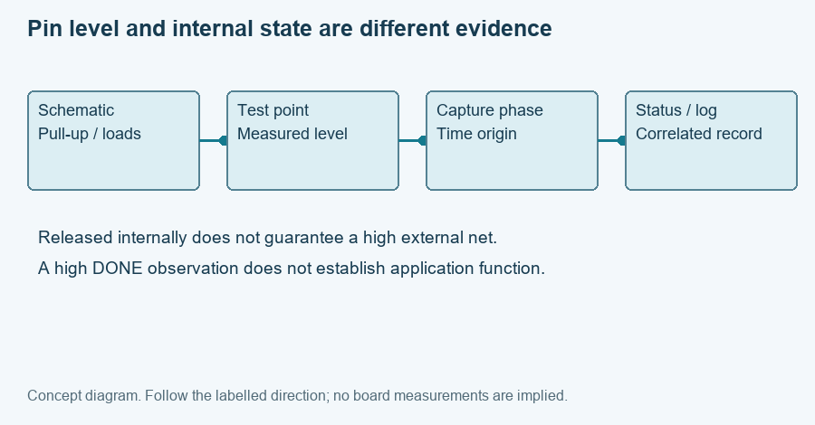
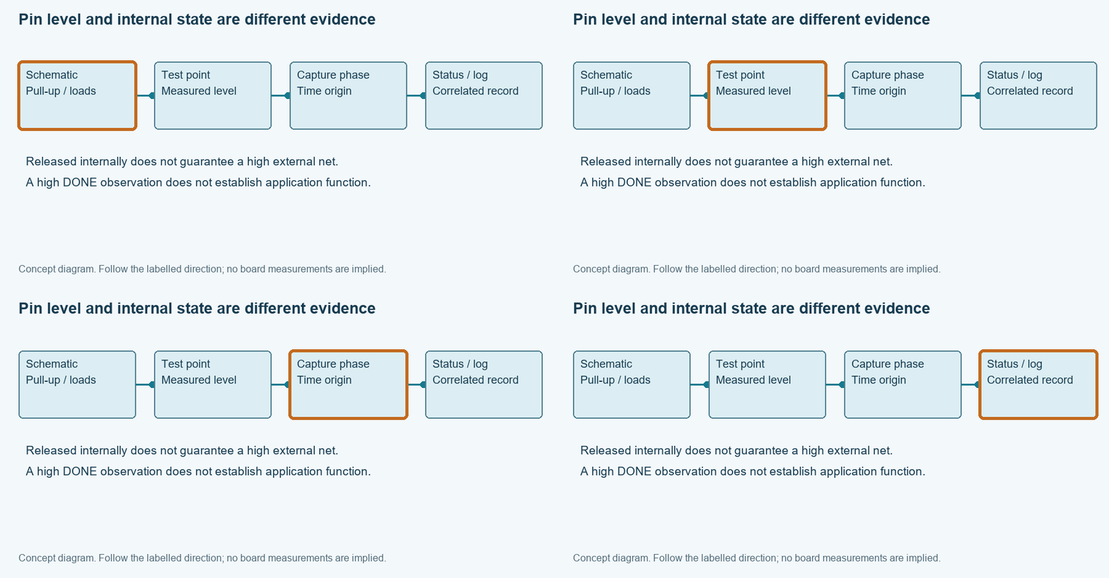
Show the diagram with each evidence item highlighted
The highlight moves between the same four items. It does not represent elapsed hardware time. Close this disclosure to hide motion; the static diagram contains the same information.
Select the observation phase and the measured INIT_B and DONE levels in the worksheet. Add the point and time of measurement. Unknown is a valid entry when a signal was not captured. The report asks for missing context rather than treating an unobserved signal as low or assuming that a software message is an external pin measurement.
The output suggests the next class of evidence: transition timing during initialization, correlation with loading errors, external loading of DONE, or application checks after both signals are high. It does not calculate pull-up values, generate package pin numbers or prescribe a voltage. Those choices require the actual board and device electrical documentation.
Keep a measurement table with columns for attempt, time origin, observation point, phase, INIT_B, DONE and associated log or capture. Add a column for any change made before that attempt. This prevents a failed boot with one image from being compared casually with a successful boot after both image and power settings changed.
Consider a hypothetical case where a meter shows DONE low after a failed start, but no transition history exists. The defensible conclusion is that DONE was low at the measurement time. The next experiment is a time-correlated capture, not an immediate declaration of CRC failure. In another hypothetical case, a capture shows a transition during loading and the tool reports an error at the same stage. That supports a more focused investigation while still leaving the physical cause to establish.
If software exposes a configuration status register, retain the raw value, exact register name, device family and capture phase alongside the pin observations. Register fields may represent internal state, sampled pins or error flags. They should not be flattened into one generic “status passed” field. Also record whether connecting the debugger or refreshing the device changes the condition being investigated.
For repeated board handling, build the observation points into the programming fixture procedure. Define which signals the fixture measures, when it samples them and what happens if the expected event does not occur. Avoid an acceptance rule that reads a pin once at an arbitrary delay and labels every low result as the same fault.
Without JavaScript, use the same phase-and-signal table manually. Write the narrow observation first, the possible interpretations second, and the next measurement third. Keeping these separate prevents a hypothesis from being copied into later reports as if it were a measured fact. It also makes contradictory evidence easier to recognize.
For an engineering discussion, provide the exported record, relevant schematic fragment and a successful/failed capture pair if available. State the unresolved question in terms of an event: initialization does not progress, loading changes the signal, DONE remains externally low, or application behavior is absent after configuration. That gives the reviewer an event to investigate instead of an unsupported component diagnosis.
Enable JavaScript for the local worksheet, or use the manual record procedure in the article. No data is submitted automatically.
Use the record for the next engineering decision
Review and download the worksheet above. For board-level help, open the engineering scope entry and include the exact board revision, observed failure and unresolved check. For an exact-part enquiry, use the component quotation entry with the complete ordering code and quantity. Opening either entry does not submit a request.
Reference scope
Prepared for the specific diagnostic task shown above. Source checks: 2026-11-14. UG470 references use v1.17; cited UG908 task pages were checked as 2026.1 where stated. Hardware commands and board behavior require verification in the actual setup. Concept figures and hypothetical examples are not measured test results.