
Tutorials
How to Choose an FPGA JTAG Programmer and Verify Compatibility
Published · Updated
Choosing a JTAG programmer starts with the exact device, the operation you need, and the software release that will perform it. A matching connector is only one part of that decision. A cable can enumerate on USB while the target remains invisible; a successful FPGA configuration can leave external boot memory unchanged. This guide turns those distinctions into a compatibility record you can use before buying a cable or debugging a board. It is a documentation and bench-check workflow, not a declaration that FPGA.io has tested the combinations described here.
Identify the Programming Task Before the Cable
Write one sentence describing the required result. “Configure this Artix-7 prototype from a computer” is different from “write its external configuration memory so that it starts without a computer.” Debugging an embedded logic analyzer introduces another requirement. An unattended production station adds scripting, stable device identification, log collection, and recovery after an interrupted operation. List these tasks separately, because a product description that mentions JTAG does not establish support for every operation.
For each task, define an observable acceptance result. Direct configuration might require the expected FPGA to be detected and a small, identifiable design to run. Persistent programming requires verification of the intended memory contents followed by an independent power-cycle test. Debugging requires the software to recognize the debug resources in the matching design. A production workflow should return a useful failure code and preserve a record even when a board is disconnected unexpectedly. These are proposed tests, not reported results.
Determine whether the board already includes a supported USB-to-JTAG interface. An onboard interface may make an external cable unnecessary for development, while a connector or test footprint is still needed for manufacturing or recovery. Check the board documentation before attaching two programmers to the same signals. The required ownership of TCK, TMS, TDI, TDO, reference voltage, and ground must be explicit.
Keep the purchase decision tied to these tasks. A faster advertised clock does not compensate for unsupported flash programming or the absence of an automatable workflow. Conversely, a simple supported cable may be sufficient when the requirement is occasional configuration of one prototype. Record expected usage, connection method, host operating system, and whether multiple identical targets must be distinguished on the same workstation. That short requirement prevents a connector photograph from becoming the entire specification.
Check Device and Software Support Together
Build a three-part evidence chain: exact target device, exact programming software release, and exact programmer model or revision. Start from the tool vendor's supported-device and cable documentation. Then check the programmer vendor's manual for installation requirements and electrical behavior. Retain document titles, revisions, relevant sections, and the date checked. An old manual can still explain a connector while being insufficient evidence for a newer operating system or tool release.
The vendor tool pages linked below provide starting points for Vivado, Quartus Prime, Radiant, and FlashPro Express workflows. They are separate ecosystems, not a list of interchangeable programmers. Even within one vendor's products, support may depend on the device generation and operation. Do not convert a statement about one family into approval for all devices bearing that manufacturer's name.
For an AMD configuration-memory task, UG908 distinguishes programming the FPGA from programming attached configuration memory. Check the memory device support for the chosen release as well as FPGA and cable support. The cable is only one element in the path. If the board uses a different memory organization, wiring, or operating mode from the documented combination, retain that as an unresolved condition instead of marking the entire setup compatible.
Use three evidence states: documented match, documented conflict, and unknown. Reserve “board validated” for an actual test record on the specified hardware and software. For example, a current tool document might establish cable support while the target reference-voltage connection remains unknown. The correct overall status is incomplete evidence. It is not a pass with a small footnote. The worksheet follows this rule so that an unanswered electrical question remains visible when the brief is copied or exported.
Map the Connector and Reference Voltage
Prepare a signal mapping from the programmer connector to the board connector and onward to the target. Include ground, reference voltage, JTAG signals, and any optional reset or control lines actually used. Use the connector orientation, mating view, and pin-one marking from the selected hardware documentation. A cable viewed from its wire side can appear mirrored relative to the board drawing. Resolve that ambiguity before applying power.
Do not treat reference voltage as a universal power output. Determine whether the programmer senses the target's I/O voltage, supplies any target power, or has a separately documented supply capability. Then identify which board rail drives that reference and when it becomes valid. Compare the specified operating range of the programmer with the target's interface voltage. A mechanical adapter cannot correct a voltage mismatch by itself.
On the schematic, follow each programming signal through buffers, series components, jumpers, and other devices in the chain. Confirm what happens when part of the board is unpowered. If a buffer requires an enable signal generated by user logic, programming an unconfigured device may be impossible through that path. This is a design question to resolve from the circuit, not a reason to increase the JTAG clock blindly.
Before the first scan, inspect orientation and use an appropriate unpowered continuity check where the board procedure permits it. After power is applied under the board's approved procedure, verify the relevant rail and reference at their actual connection points. Record instrument, location, and operating state. Do not infer a voltage from the nominal label alone. Avoid generic pin-number tables in a shared work instruction: attach the exact cable and board mapping so that a future adapter change cannot silently invalidate the procedure.
Interactive planning worksheet
The worked method remains in the article. JavaScript adds input fields and a local summary export; no data is submitted.
Compare Verified Candidates
Compare candidates against the same requirement row by row. Useful columns are programmer model and revision, vendor software release, host platform, target family, required operations, reference-voltage range, connector mapping, scripting support, and evidence status. Include an unresolved-items column. Leave commercial fields such as stock, price, and delivery marked for current quotation rather than copying a historical listing into a technical recommendation.
Consider a fictional comparison. Candidate A has a documented software match and a complete connector drawing, but its unattended scripting behavior has not been checked. Candidate B has an attractive connector and price, but its software support statement names a different device generation. For a manual prototype task, A may advance to a bench test. For a production task, neither is ready until the scripting requirement is resolved. B needs stronger compatibility evidence before electrical testing is even useful.
Avoid a weighted score that allows several minor conveniences to cancel a critical electrical conflict. Treat target-voltage compatibility, required software support, and required operation support as gates. Ergonomics, replacement availability, cable length, and station organization become comparisons after the gates are satisfied. A visible failure in a required gate should remain a failure regardless of the candidate's total score.
Preserve the reason for each decision. “Not selected because the required host release is undocumented” is more useful than “bad programmer.” Evidence can change, and a later engineer should be able to update the decision without rebuilding the investigation. The interactive checklist deliberately produces a conditional result rather than a brand recommendation. Enter one candidate at a time and export the records to compare them. No automated compatibility database is implied, and the worksheet does not fetch vendor information or certify hardware.
Investigate a Cable That Is Not Detected
Separate host detection from target detection. If the operating system cannot see the programmer, begin with the USB path, the expected device identity, and the vendor's driver installation procedure. Use a known data-capable connection and avoid changing several variables at once. Record the observed host error. Do not install an arbitrary driver package merely because a search result associates it with a similarly named cable.
If the host sees the cable but the programming application does not, inspect the supported software version, hardware-server connection, and process ownership. Another application may be holding the interface. Record which local or remote server the application is using, since a visible cable on one computer does not establish that a tool session is connected to that computer. Use the vendor's documented recovery procedure before repeatedly reconnecting hardware.
If the application sees the cable but not the FPGA, return to target power, reference voltage, wiring, chain order, and reset or enable conditions. Compare the observed chain with the schematic's expected device order. A lower scan clock can be a controlled diagnostic experiment when documented by the tool, but it does not prove signal integrity or repair a wrong connection. Save both the original and changed clock values with their outcomes.
Once a scan works, use a minimal known project with an identifiable version and a safe observable result. Keep its constraints appropriate to the exact board. If the project works only after manually changing resets or straps, write those changes into the record; they are part of the environment. A reproducible failure stage is valuable even before the fault is found. “USB enumerates, application opens cable, chain scan returns no target” directs the next investigation far better than “programmer broken.”
Export a Compatibility Brief
Use the worksheet to collect the target, candidate programmer, software release, intended operation, and evidence gates. Export both successful matches and unresolved conditions. Include the source references and attach the actual connector mapping when sharing the brief. The tool's output is a planning record: its documented-match result means that the entered answers contain no reported conflicts, not that those answers have been independently verified.
For a bench qualification, define the board revision and serial identifier, image hash, host environment, connection arrangement, and acceptance steps before starting. Save detection logs, programming and verification results, and the observation that proves the intended design ran. Repeat the test after a complete disconnect when persistent operation matters. A successful direct configuration and a successful flash boot belong in separate fields so that one cannot be mistaken for the other.
For purchasing, provide the exact programmer identity, required accessories, quantity, destination, and the compatibility conditions that remain open. For engineering assistance, provide the board mapping and the earliest failing stage. Use the device or project enquiry entry only after reviewing the copied summary. The page does not submit enquiries, and exporting a checklist does not reserve stock or establish a delivery promise.
If JavaScript is unavailable, reproduce the same worksheet in a text file: mark every required gate as match, conflict, or unknown, list the evidence for each mark, and keep bench validation separate. Any conflict blocks the candidate; any unknown requires another check. Only a completed board-specific test can close the validation field. This simple discipline also answers the most common purchasing question: a universal-looking JTAG connector is not enough to establish a supported programming solution.
Sequence illustration and static alternative
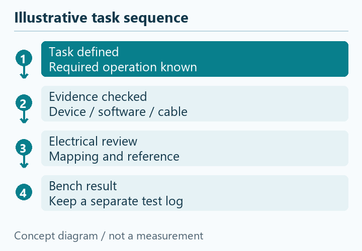
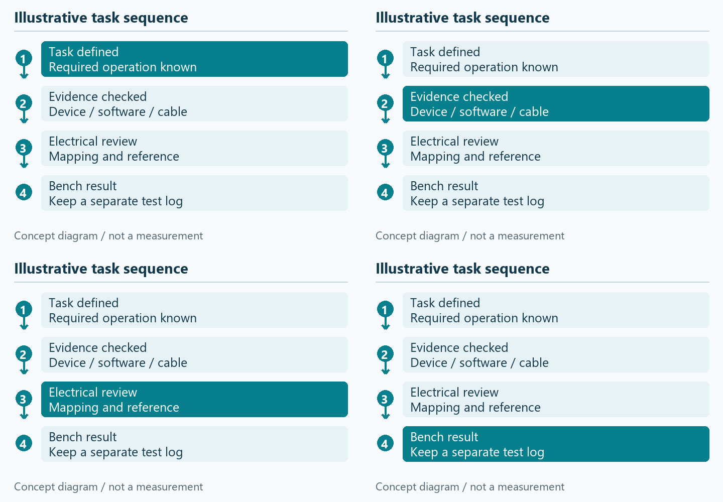
Concept animation: highlighted stages show the order of checks, not elapsed time or a measured hardware result. Close the disclosure to hide motion. The numbered static diagram provides the same sequence.
Show the short illustrative animation
Continue the specific engineering task
- vivado — Review this vendor-specific software workflow; support remains release-dependent.
- quartus prime — Review this vendor-specific software workflow; support remains release-dependent.
- radiant — Review this vendor-specific software workflow; support remains release-dependent.
- flashpro express — Review this vendor-specific software workflow; support remains release-dependent.
- Prepare an engineering review — Use this related method or service to resolve the next requirement.
Prepare an enquiry after reviewing the result
Copy or download your worksheet first. Include the exact part, quantity and unresolved conditions for a component enquiry, or board revision, requirements and test scope for a project discussion. These links open the enquiry entry; this page does not submit a request or promise automatic prefill.
Open the component enquiry entry · Discuss the engineering scope
Source scope and editorial method
Vivado UG908 — Programming Configuration Memory Devices is the primary manufacturer reference for this article. Source check: 2026-11-13. This article presents planning methods; it does not establish measured prototype results, current stock or delivery availability.
Additional reference addresses (plain text; scope must be checked for the selected board and software):
Digilent JTAG-HS2 reference manual — https://digilent.com/reference/_media/jtag_hs2%3Ajtag-hs2_rm.pdf