
Tutorials
Artix-7 MultiBoot Fallback: Plan the Golden and Update Images
Published · Updated
An update image can configure successfully and still fail to perform its application task. Decide whether that case is in your recovery design before calling it a fallback solution. Hardware configuration fallback and product-level health recovery have different triggers and responsibilities.
Decide which failures the design must survive


List failures by stage: the update transfer was interrupted, the stored image cannot configure, configuration completes but the application fails, or the recovery image itself is unavailable. Assign an observer and recovery action to each. One successful demonstration does not cover the whole list.
UG470's MultiBoot chapter is the mechanism reference for the stated 7 Series scope. Do not transfer assumptions from PolarFire or an Alveo recovery procedure to an Artix-7 design. Similar terms such as golden image can conceal different implementation details.
| Injected fault | Question the design must answer |
|---|---|
| Update stops during transfer | Does a usable recovery image survive the actual erase/write sequence? |
| Update cannot configure | Which documented configuration fallback condition applies? |
| Configuration succeeds; application stalls | Which application monitor detects the failure and requests recovery? |
| Golden image is damaged | Which independent access route can restore it? |
For a concrete density example, review the XC7A100T device scope; board-level recovery still needs its own design.
When a temporary load runs but startup fails, separate JTAG and flash boot before blaming the recovery policy.
Protect the recovery path
Define where the recovery image is stored, how it is protected during updates and which access path remains if the normal application is unavailable. Review the programmer's erase scope as well as the byte layout. Separate files can still occupy an erase region that an update affects.
Preserve a usable external recovery route when the product requires it. Identify the physical connector, board power conditions and any access restrictions. A schematic label saying JTAG does not establish that a field technician can reach or use it.
Record the exact Flash and configuration mode. Do not assume that a larger memory or a different interface width preserves the same startup and fallback behavior without checking the device guide and tool support.
Before placing golden and update slots, budget recovery images with room for the planned images.
Trace the boot and fallback states
Draw the intended states and transitions, then label which transitions are supplied by the FPGA configuration mechanism and which require product logic or an external supervisor. A diagram with every arrow labelled automatic hides the most important design decisions.
Keep a distinct branch for application health after configuration. If the design requires detection of an unresponsive data path, specify what observation detects it, what deadline applies and who can request recovery. Those are product acceptance requirements, not consequences of a successful configuration alone.
A damaged or erased recovery image is not repaired merely by selecting it again. The design review must identify what can restore it and what evidence proves that route remains available.
During fault injection, interpret configuration status against the exact attempt under test.
Turn the design into a fault-injection plan
For each fault, record the starting image, trigger, expected observation, recovery action and final acceptance check. Include interrupted updates and failures that occur after configuration has apparently succeeded. Use controlled test conditions and preserve records rather than presenting a conceptual state diagram as a measured result.
Observe configuration status and relevant pins through the documented board procedure. Link the observations to the particular attempt; an old status capture can describe a previous failure rather than the current one.
The coverage worksheet identifies missing responsibilities and untested cases. It does not certify an update architecture. Export the matrix with the memory map and recovery-access assumptions for a design review.
At the board, observe INIT_B and DONE using the documented connection and timing procedure.
Technical references for this scope: AMD UG470 v1.17 (2023-12-05); AMD UG908 2024.1 — Programming a Configuration Memory Device.
Highlight the three review items
Each highlight marks one item to review, not elapsed hardware time. The static figure contains the same information.
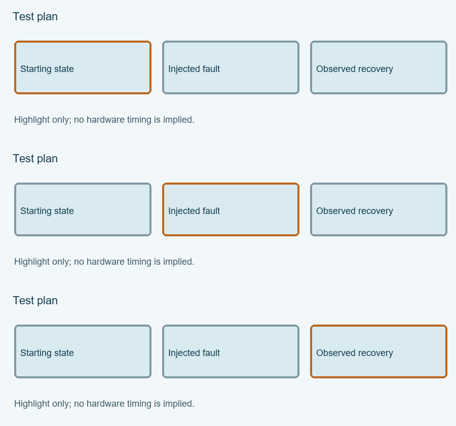
Enable JavaScript for the local Fallback coverage matrix. The article above provides the manual procedure; no data is submitted automatically.
Review and export your result before opening the engineering discussion entry. Attach the exported text yourself; opening the entry does not submit it.
Reference scope checked 15 November 2026. Calculations and conceptual diagrams describe the stated model. Commands and board behavior require validation in the actual tool and board environment.