
Tutorials
FPGA FIFO Overflow Debugging: Capture the First Rejected Write
Published · Updated
Define what your overflow indication actually means
“Overflow” can mean a write was attempted while full, that an input beat was dropped upstream, or that a custom ring overwrote unread data. Those are different faults. In a FIFO that rejects writes while full, an overflow indication does not by itself mean stored entries were overwritten.

Document the interface acceptance rule. For a conventional native FIFO this may be write-enable while not full, subject to reset and macro-specific rules. AXI4-Stream acceptance is a valid-and-ready handshake. A source continuing to change samples when it cannot transfer needs an explicit loss policy; the FIFO cannot recover a sample it never received.
Revisit the acquisition-rate assumptions.
Plan accessible probe points before capture.
Freeze the first failure instead of only counting the last one
Capture a short pre-trigger window and latch the first error record: cycle or timestamp, reset state, write request, full, read request, empty, accepted counters and relevant source sequence number. Add high-water occupancy if the implementation exposes a trustworthy value. A final total of 4,096 errors is much less useful than the conditions immediately before the first one.
The local log checker expects cycle,wr_req,full,rd_req,empty,reset columns with binary flags. It reports the first full-time write request and empty-time read request outside reset. These are request diagnostics under a stated conventional interface, not proof of overwritten memory. Do not feed an AXI trace into that schema without first deriving the corresponding request and acceptance signals.
Use the evidence to select the next experiment
If the first error follows a long consumer pause, compare the pause against the capacity budget. If it occurs during reset, inspect the documented reset-busy sequence. If accepted counts balance but sample identifiers skip, examine the source and packet framing. If the trace is missing the relevant clock-domain observation, collect that evidence before changing FIFO depth.
Keep the raw log beside the configuration and bitstream identity. The checker operates locally in the page and exports a summary; it does not transmit your capture. Replace repeated “overflow happened” messages with one preserved first-error snapshot plus a separate running count, so later events cannot erase the earliest evidence.
Preserve the first rejected request: short sequence
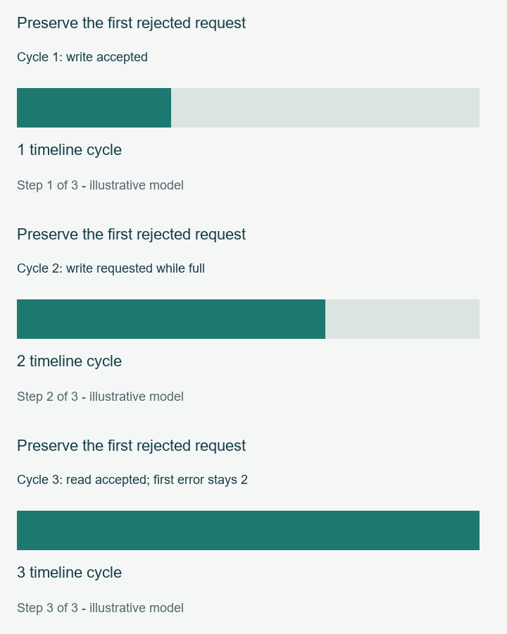
Cycle 1: write accepted: 1 timeline cycle → Cycle 2: write requested while full: 2 timeline cycle → Cycle 3: read accepted; first error stays 2: 3 timeline cycle
Export your result with its assumptions. For an unresolved board or implementation issue, prepare an engineering review with the exact part, revision and relevant record. This link opens the review page; it does not send your worksheet.
Sources and scope
Sources checked 18 November 2026. Numerical examples are calculated cases. Hardware measurements and device timing closure are outside the results shown here.
Back to Tutorials