
Tutorials
Asynchronous FIFO Flags: Why Full and Empty Do Not Update Together
Published · Updated
An asynchronous FIFO has two local views
After a write, the read side can still report empty for a while. After a read frees a slot, the write side can still report full. This need not indicate corruption. Each side makes decisions using local information and a synchronized view of progress in the other domain.
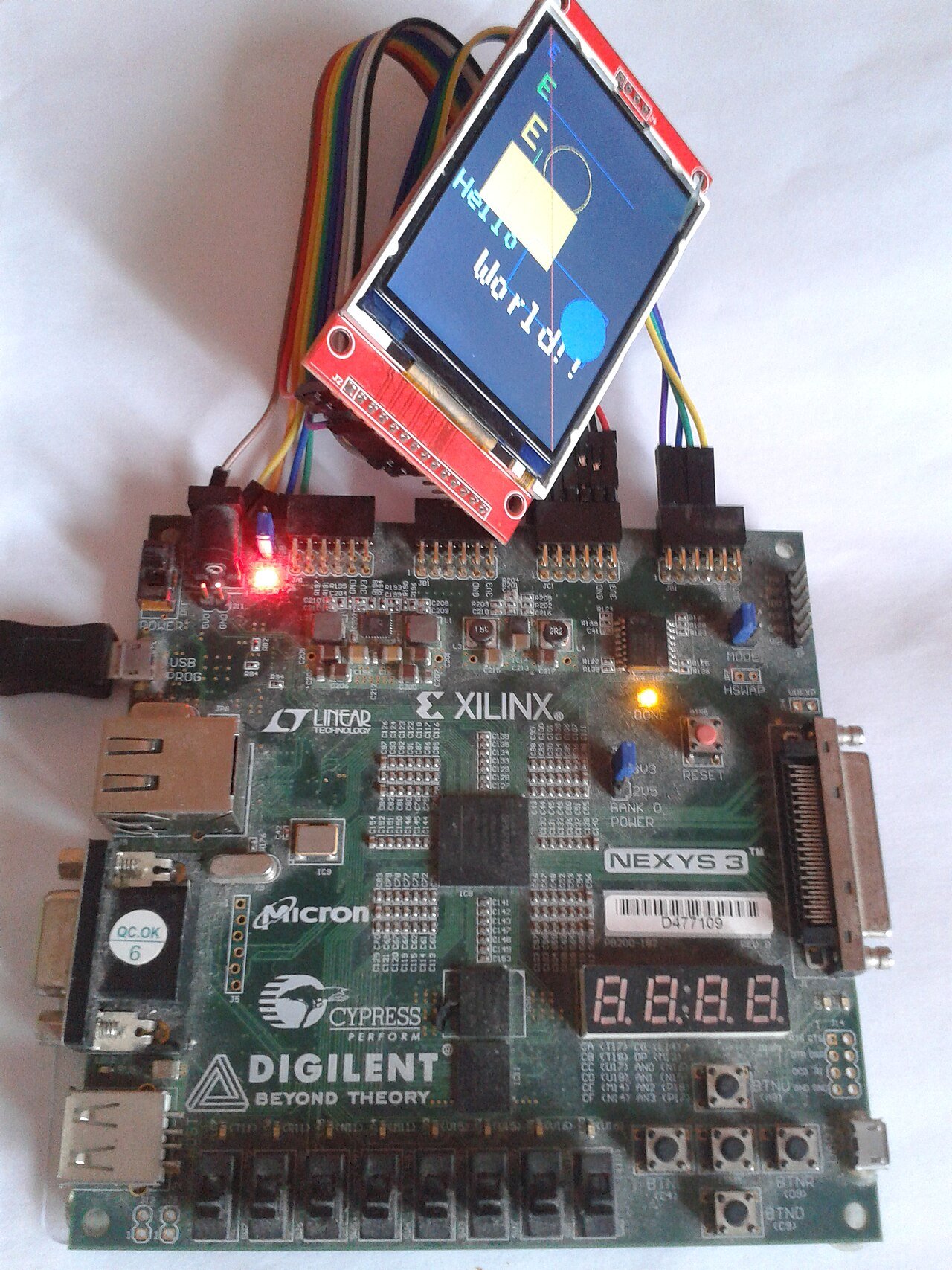

First identify which clock owns the signal you captured. A write-domain full flag and a read-domain empty flag are not two simultaneous measurements from a single global occupancy meter. Keep write attempts, accepted writes, read attempts and accepted reads separate in the trace. Also record whether either clock stopped.
Review what a single-bit synchronizer does.
Define the actual clock constraint.
Use a crossing model to understand phase, then check the IP
The timing explorer below models a registered event passing through a configurable number of destination-clock sampling stages. Move the source event across a destination edge and observe the change in visibility. An event exactly on an edge is shown as a boundary case, because a digital timestamp alone does not establish physical setup and hold margin.
That model is deliberately narrower than a complete FIFO. AMD XPM_FIFO_ASYNC behavior also depends on read mode, output latency, synchronization settings and the particular flag. FIFO Generator has its own configuration and documentation. Do not convert “two synchronizer stages” into a claim that every flag changes exactly two cycles later.
Check reset release in each domain.
Capture the configuration beside the waveform
Save the exact macro or IP version, clocks, READ_MODE, configured latency and synchronization-stage count with the trace. Include reset and reset-busy indications, and wait for the documented operating condition before issuing traffic. A trace without that context can make normal startup look like a missed word.
For a useful test, sweep clock ratio and phase, then pause one clock in a controlled simulation case. Verify data order with a scoreboard in addition to inspecting flags. This article does not recommend constructing a multi-bit crossing from independent single-bit synchronizers; use a reviewed FIFO architecture and its constraints.
Ideal two-stage crossing: short sequence
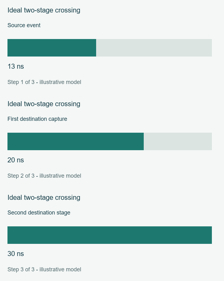
Source event: 13 ns → First destination capture: 20 ns → Second destination stage: 30 ns
Export your result with its assumptions. For an unresolved board or implementation issue, prepare an engineering review with the exact part, revision and relevant record. This link opens the review page; it does not send your worksheet.
Sources and scope
Sources checked 18 November 2026. Numerical examples are calculated cases. Hardware measurements and device timing closure are outside the results shown here.
Back to Tutorials