
Tutorials
Vivado Cannot Find a Hardware Target: Where to Start
Published · Updated
Vivado can reach a hardware server without finding a cable, and it can list a cable without finding the FPGA. Those are different failures. Before reinstalling software or rebuilding a bitstream, write down the last object that Hardware Manager actually discovered. The useful first question is not “Why does JTAG fail?” It is “Which boundary has not been crossed?”
This guide separates the client, server, cable target and device scan. The worksheet at the end turns those observations into a next check and a shareable record. It cannot interrogate a connected board. Leave an unmeasured item unknown; a missing observation is not evidence of a failed component.
Open the diagnostic worksheet ↓
Identify the missing connection boundary
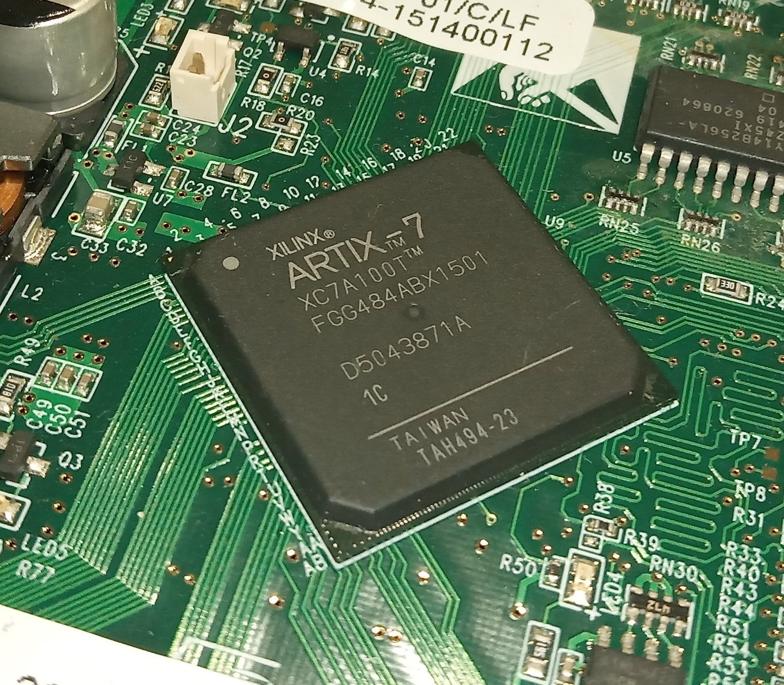

A useful bench record begins with physical identity. Photograph the target board, identify its revision, record the FPGA marking, and note which cable reaches which connector. A cable plugged into a nearby board can produce a perfectly plausible target list. Likewise, two identical USB programmers can be difficult to distinguish from an abbreviated software label. Include serial numbers or another stable identifier before accepting a result from an automatically selected target.
The Artix-7 photograph here illustrates the device-identification step. It is not a wiring diagram for your board. Its FGG484 package must not be confused with a CSG324 device simply because both markings contain XC7A100T. The site’s XC7A100T-1CSG324C device page is a useful example of a complete ordering code; use the exact installed code in your own record. Neither package appearance nor successful enumeration proves every ordering attribute.
Start with the host arrangement. Does the programming cable attach to the computer running Vivado, or to a separate lab computer? In the second arrangement, the cable drivers and server process belong on the lab computer. Reinstalling a driver on the client may have no effect on the system that owns the cable. Draw the two computers separately if another engineer will reproduce the setup.
Then record four observations in order: whether the server session connected; whether the intended cable target appeared; whether opening that target returned any devices; and whether the expected FPGA appeared in the correct context. Save the complete message at the first failed step. “No target” is too broad to preserve the distinction between an unreachable server and a responsive server reporting an empty list.
For example, suppose the server connection succeeds and a programmer serial number appears, but the device list is empty. That observation moves the next investigation toward the target connection and chain. It does not prove that the FPGA is damaged. If no programmer appears at all, measuring an application clock on the FPGA is unlikely to answer the immediate enumeration question. These are decisions about the next measurement, not verdicts about the final root cause.
AMD’s UG908, Opening a New Hardware Target, describes local and remote selection and the distinction between targets and devices. The cited page was checked as version 2026.1. Menu placement can differ between releases, so retain your actual release in the report instead of treating a screenshot from another version as an exact instruction.
If the display might be stale, capture it before refreshing, then repeat the same discovery operation and timestamp the new result. Do not combine a device name from an earlier successful session with a current server error. A chronological record is often more informative than a single screenshot containing both old objects and new messages.
Test the next boundary without changing the whole setup
When the server session is absent, first verify the intended endpoint and which machine should run the server. Record both client and server versions, the error text, and whether the error is immediate or follows a timeout. Changing a bitstream cannot repair an unestablished server session. A controlled server check should leave board wiring and programming files untouched so its result has a clear interpretation.
When the server connects but the cable target is absent, inspect enumeration on the server host. Confirm the cable model, supported connection method and driver requirements for the chosen software release. The JTAG programmer compatibility checklist helps distinguish connector compatibility from actual software support. Matching a header shape is not enough. An adapter can map signals while the cable itself remains unsupported by that toolchain.
Also establish whether another application owns the cable. Coordinate access with the lab operator before closing anything. A shared workstation can have a running programming task that is not visible in your client window. Record what was using the cable and what changed; otherwise a successful reconnect after several unrelated actions teaches very little about the failure.
When the cable is listed but devices are missing, move to the board side. Check the board’s documented power sequence, actual power state, cable reference-voltage requirements and connector orientation. A lit LED shows something about its own circuit, not necessarily every rail needed by the scan path. Use the schematic and measurement points for that board revision. Do not infer a safe I/O voltage from the connector label or from a different development board.
Compare the physical chain with the intended chain. Include devices that sit between the programmer and FPGA, optional links, isolation buffers and jumpers. An unpowered intermediate device can matter even when the FPGA itself is powered. Take a photograph of the actual jumper state and preserve the reference designators. A statement such as “the jumpers are normal” becomes ambiguous when assembly revisions change.
A lower supported TCK setting can be a useful experiment when identification is unreliable, but change only that setting for the comparison. AMD’s target troubleshooting guidance discusses frequency and unknown-device instruction lengths. A successful slower scan is evidence of a condition-sensitive path; it is not a universal repair or proof that the selected frequency has adequate production margin.
Use a known working setup carefully. Swapping both the cable and board at once can show that the replacement combination works, but it does not isolate which original item matters. Prefer a small matrix: original cable with reference board, then reference cable with original board, keeping the software host and connection procedure fixed. Only make swaps that are electrically compatible and allowed by the board procedure. Label each run so observations cannot drift between setups.
Stop at the first new evidence. If the FPGA now enumerates, save the result before trying programming. Discovery, configuration and application behavior are separate tests. Combining them into one pass/fail result makes it harder to tell which stage improved and whether a later problem is unrelated.
Export a connection record that another engineer can reproduce
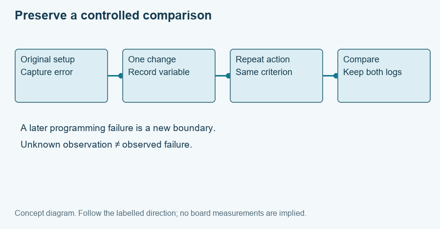
Show the diagram with each evidence item highlighted
The highlight moves between the same four items. It does not represent elapsed hardware time. Close this disclosure to hide motion; the static diagram contains the same information.
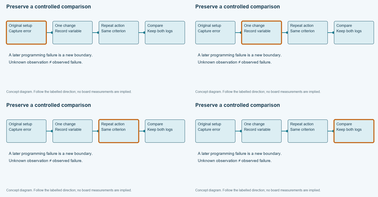
The worksheet follows the same sequence as the bench procedure. Select the current server result, current cable result and current device result. Add the board revision, exact device, tool release and notes. The output chooses the earliest unproven boundary and explicitly lists unknown observations. It does not test USB, open a network connection, read JTAG or certify a programmer.
Before sharing the output, add the complete error message and the action that produced it. Include whether this was a cold start, a reconnect after programming, or a session opened while another tool was running. These details distinguish failures that look identical in a short screenshot. If the message contains a private host name, replace it consistently in the shared copy while retaining the original in the controlled lab record.
A useful reproduction instruction is specific enough to be repeated: connect the identified cable to the identified board connector, apply the documented supply setup, start the stated client/server release, select the recorded endpoint, and perform the stated discovery action. Then describe the expected object and the actual object. “It should work” is not an expected result; “one FPGA with this recorded ID appears on this cable target” is testable.
Keep screenshots and text together. A screenshot establishes which UI objects were visible, while copied text preserves long errors and exact identifiers. Record the capture time and label repeated attempts. If the next engineer cannot tell whether an image came before or after a cable swap, the report has lost the experiment’s most important distinction.
The FPGA PCB bring-up checklist provides the broader board-level context when power or test access remains uncertain. For repeated work across many boards, the programming fixture guide turns the connection procedure into defined contacts, checks and traceability. A fixture should preserve evidence from failures, not just collect successful programming counts.
If JavaScript is unavailable, copy the four connection observations into a text file and identify the first unknown or failed boundary manually. Add one proposed check, the variable it changes, and the observation that would support or weaken your hypothesis. This produces the same practical output as the worksheet. Do not mark a missing field as passed just to make a report appear complete.
After a successful discovery, preserve the working record as a baseline with a date and setup identity. Future failures can then be compared against something concrete: a changed software release, cable extension, host, board revision or power procedure. “It worked last week” becomes useful only when last week’s conditions are recoverable.
For an engineering discussion, export the record and identify the decision you need help with: cable support, board access, chain identification or a reproducible fixture procedure. A focused request with the first unproven boundary gives the reviewer a starting point. A list of every attempted fix usually does not.
Enable JavaScript for the local worksheet, or use the manual record procedure in the article. No data is submitted automatically.
Use the record for the next engineering decision
Review and download the worksheet above. For board-level help, open the engineering scope entry and include the exact board revision, observed failure and unresolved check. For an exact-part enquiry, use the component quotation entry with the complete ordering code and quantity. Opening either entry does not submit a request.
Reference scope
Prepared for the specific diagnostic task shown above. Source checks: 2026-11-14. UG470 references use v1.17; cited UG908 task pages were checked as 2026.1 where stated. Hardware commands and board behavior require verification in the actual setup. Concept figures and hypothetical examples are not measured test results.