
Tutorials
Verilog Counter Testbench: Catch Wraparound, Reset and Enable Bugs
Published · Updated
A counter that increments correctly for a few cycles can still fail at wraparound, hold, reset priority or a parameter boundary. A useful testbench computes an independent expected value and checks it after sequential updates, rather than relying on a waveform that looks plausible.
Define the counter before testing it
This example counts from 0 through MODULUS−1. Reset is synchronous and active high; reset wins over enable. When enable is low, the count holds. MODULUS must be positive, and the output width is at least one bit, including MODULUS=1. These choices are part of the interface contract, not properties shared by every counter.


The Nexys 3 photograph shows displays and user controls that can make a count visible. Watching a display increment would not prove the boundary conditions below. This article supplies a simulator test, not a hardware project for that photographed board.
The RTL uses a comparison against MODULUS−1 and an explicit wrap to zero. That matters for MODULUS=10: a four-bit register would otherwise roll over at sixteen. The download contains the complete module and a parameterized testbench. Read the assignment-coverage example if a separate combinational next-state block is being used.
Drive away from the sampling edge
@(negedge clk); rst=r; en=e;
@(posedge clk);
if (r) expected=0;
else if (e) expected=(expected+1)%M;
#1; // after nonblocking updates; testbench timescale is 1ns/1ps
if (count !== expected[W-1:0])
  $fatal(1,"counter mismatch");
Inputs change on the falling edge, and the testbench checks one nanosecond after the rising edge. With this example’s 10 ns clock, the observation occurs after nonblocking assignments have updated the design and before the next falling edge. The delay is a testbench scheduling choice, not a hardware delay to synthesize.
The reference model uses integer modulo arithmetic instead of copying the RTL comparison-and-wrap branches. The case-inequality operator also catches X or Z output bits. A check that compares only known values can accidentally let an uninitialized signal slip through.
Reset is applied before judging normal operation. The initial register state is not assumed. Each step records its expected value, and a failure prints the modulus, check number, observed value and expected value before terminating. A timeout also prevents a hung test from looking like a successful run.
The distinction between synchronous reset behavior and domain-local reset release is covered in the reset article.
Exercise the awkward parameter values
| MODULUS | Why it is included | Observed checks |
|---|---|---|
| 1 | Minimum legal width and constant-zero wrap | 11 |
| 2 | Small power-of-two boundary | 14 |
| 3 | Small non-power-of-two wrap | 17 |
| 10 | Decimal counter case | 38 |
| 16 | Exact power-of-two wrap | 56 |
All five runs passed in Icarus Verilog from OSS CAD Suite 2026-11-15. Each run includes reset with enable high, a disabled cycle after reset, more than three complete count periods, consecutive disabled cycles, another reset with enable high and a subsequent increment. The 136 checks establish those tested behaviors; they are not exhaustive formal verification.
iverilog -g2012 -s tb_counter -Ptb_counter.M=10 \
  -o counter.vvp mod_counter.sv tb_counter.sv
vvp counter.vvp
Repeat with M=1, 2, 3 and 16. A production variant with load, up/down, saturation or terminal-count pulses needs additional assertions for those features. Do not reuse this passing result as evidence for a modified interface.
Build a boundary sequence before running the test
The sequence tool below exposes the expected count after reset, hold and increment actions. It is a reference-model aid for planning a test, not an HDL simulator. Download the actual files for execution. For timing sign-off, separately check the clock constraint and analysis coverage. A functionally correct counter can still be part of a failing implementation path.
Counter reference-sequence builder
Inputs and exported records stay in this browser. The check evaluates the assumptions you enter; it does not inspect your project files.
Use the worked values and equations above, or download the examples below. The interactive check requires JavaScript.
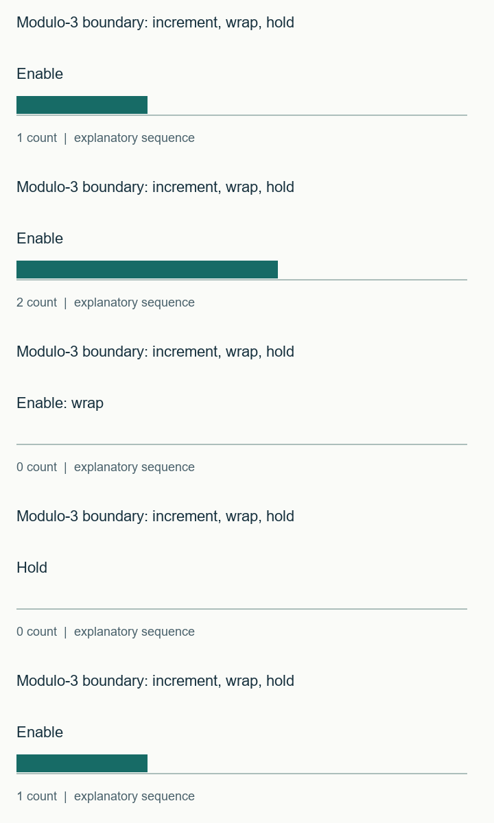
Watch the short modulo-3 boundary: increment, wrap, hold sequence
The sequence visualizes the stated example. It is not a hardware capture. The static figures and text above contain the same explanation.
Download the counter and testbench, then add checks for the features in your own interface.
Download the timing and RTL examples (ZIP) · Discuss this engineering task
The ZIP includes the clock and I/O examples, timing-audit commands, counter/latch/reset RTL and testbenches. Bring the relevant exported record to the enquiry; this page does not submit it automatically.
References and example scope
Documentation checked 16 November 2026. AMD examples use the cited 2024.1 documentation baseline. Vivado commands and vendor macros were not executed for this article. Counter, latch and illustrative reset tests were executed with Icarus Verilog; latch structure was checked with Yosys. See the included commands and validation record for the exact scope.