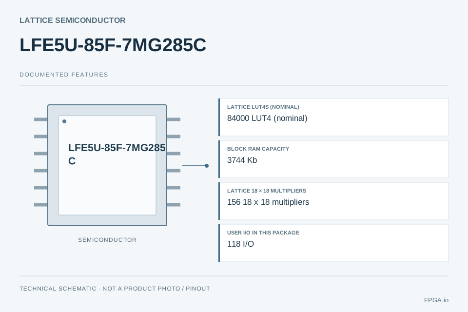
- Lattice LUT4s (nominal)
- 84000 LUT4 (nominal)
- Block RAM capacity
- 3744 Kb
- Lattice 18 × 18 multipliers
- 156 18 x 18 multipliers
- User I/O in this package
- 118 I/O
No verified supplier stock or price is currently displayed here. Request a quotation for your quantity and required delivery date.
Supplier references are independent of FPGA.io inventory. Confirm currency, region, quantity tier, packing, taxes, freight and final terms at source.
Check this exact MPN at external distributors
Search links do not establish stock, price or an authorized distribution relationship. Check the full code, package and grade at the source.
Already have a target price or delivery date? Request a Better Quote ↗
PRODUCT OVERVIEW
About LFE5U-85F-7MG285C
LFE5U-85F-7MG285C is an FPGA in the Lattice Semiconductor ECP5 family, supplied in the MG285 package. Its reviewed resources include 84,000 LUT4 (nominal), 3,744 Kb of block RAM, 118 I/O for this device/package combination. This ordering code specifies speed grade -7 and Commercial (C) temperature grade. The selected device/package has 0 SerDes channels; check this package-level limit before planning serial interfaces. Use the linked manufacturer data sheets for electrical limits, pin assignments and timing. FPGA.io can review the complete part number for chip sourcing or a combined sourcing and PCBA project.
- Lattice LUT4s (nominal)84,000 LUT4 (nominal)
- Block RAM capacity3,744 Kb
- Lattice 18 × 18 multipliers156 18 x 18 multipliers
- User I/O in this package118 I/O
- Package codeMG285
- Junction temperature (Tj)0 to +85 °C
Review parameter sources and conditions ↓Technical specifications
Core device/package/grade facts checked against official sources. Native resources are not cross-vendor equivalents. Detailed timing, design power and current supply status require project review.
Logic & memory
Native architecture resources
Package & interfaces
Operating conditions
Supply & status
ENGINEERING SELECTION
What these specifications mean for your design
Use the documented resources of LFE5U-85F-7MG285C to frame a design review. The guidance below interprets the source data; it does not establish achieved system performance.
Logic implementation
84,000 LUT4 (nominal)
Use this native resource count for an initial budget. LUT, logic-cell and logic-element definitions differ; synthesize your HDL in the target toolchain to establish fit and timing.
Manufacturer evidence ↗ Conditions ↓Buffers and local storage
3,744 Kb
Budget sample buffers, FIFOs and coefficient storage in bits, then check memory block geometry, port widths, clocking and reserved capacity. External memory needs a separate interface review.
Manufacturer evidence ↗ Conditions ↓Arithmetic and signal processing
156 18 x 18 multipliers
Map the required multiply/accumulate operations, operand widths and pipeline stages to the documented DSP architecture. A resource count does not establish throughput.
Manufacturer evidence ↗ Conditions ↓Board connections
118 I/O
This count applies to the selected device/package. Budget required signals and spare capacity, then check bank voltages, differential pairs, dedicated pins and configuration use in the pinout guide.
Manufacturer evidence ↗ Conditions ↓High-speed serial planning
0 SerDes channels
No dedicated serial transceiver channels are documented for this device/package. Do not assume another package’s transceiver capability applies; evaluate a different documented part or a separate interface device.
Manufacturer evidence ↗ Conditions ↓PCB and assembly planning
MG285
Check the official footprint, pin/ball map, pitch, escape routing, power/ground distribution and assembly constraints. Package name or ball count alone does not prove pin compatibility.
Manufacturer evidence ↗ Conditions ↓Operating environment
0 to +85 °C
Check whether this range is specified at junction or ambient, together with the source conditions. Estimate power and cooling for your design before selecting the temperature grade.
Manufacturer evidence ↗ Conditions ↓Application paths to evaluate
These are engineering evaluation directions based on documented resources, not verified reference designs or application certifications.
Control and interface logic
Evaluate state machines, parallel interfaces and I/O expansion against the documented I/O budget, bank standards and timing. Select external level shifting or interface devices where required.
Build a resource budget →Buffered signal processing
Evaluate filters, sample buffering and pipelined arithmetic using the documented DSP and block RAM resources. Validate precision, memory bandwidth, clock closure and application power in the actual implementation.
Build a resource budget →Achievable clock frequency, power consumption and interface performance depend on the implemented design, operating conditions and timing closure. Use the applicable electrical data sheet and vendor analysis tools.
Before placing this part on a board
- Use the full ordering number. Check the package pinout, power banks, speed grade and temperature range together.
- Complete timing and power analysis. A resource table cannot predict achievable frequency or application power.
- Define the manufacturing scope. Share the BGA footprint, stack-up, assembly requirements and test plan with your PCBA request.
Plan assembly for your FPGA board →
FROM SELECTION TO A BOARD
Design resources & implementation options
When to evaluate another implementation
For software-heavy control with limited parallel I/O, assess an MCU or processor against the same latency, interface and power requirements. For wide parallel datapaths or custom timing, compare FPGA architectures using a mapped design. For early prototyping, an evaluation board may reduce initial hardware work; verify its exact device, accessible interfaces and production suitability.
Explore semiconductor brands and product categories →ENGINEERING SHORTLIST
Screen candidates for your design
Start with this package’s I/O, block RAM and serial channel counts, or enter your actual requirements. Native resource requirements apply only to the selected architecture.
173 full MPNs meet the entered numeric constraints. Showing 4 device representatives, at most two per manufacturer, ordered by smallest excess resources. Temperature and package variants still need selection.
84000 LUT4 (nominal) · MG285 · Commercial (C)
Differences and compatibility checks
- Speed grade: -7 → -6. Verify the applicable limits and design impact.
Numeric matches do not establish pin compatibility, protocol support, lifecycle or supply availability.
101440 logic cells · CSG324 · Commercial (C)
Differences and compatibility checks
- Different family or manufacturer: review native logic/DSP architecture, HDL/IP portability and toolchain.
- Package: MG285 → CSG324. Verify the applicable limits and design impact.
- Speed grade: -7 → -1. Verify the applicable limits and design impact.
Numeric matches do not establish pin compatibility, protocol support, lifecycle or supply availability.
84000 LUT4 (nominal) · MG285 · Commercial (C)
Differences and compatibility checks
- Speed grade: -7 → -6. Verify the applicable limits and design impact.
Numeric matches do not establish pin compatibility, protocol support, lifecycle or supply availability.
65600 logic cells · FBG484 · Commercial (C)
Differences and compatibility checks
- Different family or manufacturer: review native logic/DSP architecture, HDL/IP portability and toolchain.
- Package: MG285 → FBG484. Verify the applicable limits and design impact.
- Speed grade: -7 → -1. Verify the applicable limits and design impact.
Numeric matches do not establish pin compatibility, protocol support, lifecycle or supply availability.
Numeric screening is not replacement approval.Logic and DSP mapping, pinout, bank voltages, temperature, timing, protocol support and toolchain remain engineering checks. Serial channel quantity does not verify data rate or protocol support. Cross-brand candidates generally require board and HDL review.
Request a board and sourcing review →
DEVICE & PROCUREMENT QUESTIONS
LFE5U-85F-7MG285C FAQ
What is LFE5U-85F-7MG285C?
LFE5U-85F-7MG285C is an FPGA in the Lattice Semiconductor ECP5 family, supplied in the MG285 package. Its reviewed resources include 84,000 LUT4 (nominal), 3,744 Kb of block RAM, 118 I/O for this device/package combination. This ordering code specifies speed grade -7 and Commercial (C) temperature grade. The selected device/package has 0 SerDes channels; check this package-level limit before planning serial interfaces. Use the linked manufacturer data sheets for electrical limits, pin assignments and timing. FPGA.io can review the complete part number for chip sourcing or a combined sourcing and PCBA project.
Which package and grade does LFE5U-85F-7MG285C specify?
The reviewed package is MG285 and the temperature grade is Commercial (C). The documented operating range is 0 to +85 °C. Recommended operating junction temperature Tj. This is not ambient Ta, storage temperature, or the absolute maximum junction rating. Match the complete suffix when preparing a BOM.
Where can I find the official LFE5U-85F-7MG285C datasheet?
Use the manufacturer-hosted PDF and documentation links in Official documents on this page. The electrical data sheet, resource overview and package/pinout guide serve different purposes; check the relevant revision and tables together.
Is LFE5U-85F-7MG285C in stock, and can I request a better price?
FPGA.io confirms price, available quantity, lot requirements and lead time through a quotation. Supplier references are separate from FPGA.io stock. Send your required quantity and delivery date; an optional target unit price helps us assess a price-review request. A lower price is not guaranteed.
Can another FPGA replace LFE5U-85F-7MG285C?
A similar resource count does not establish compatibility. Compare package pinout, I/O-bank voltages, configuration, timing, temperature grade and tool support. The candidate screen is a starting point for engineering review, not replacement approval.
Can FPGA.io supply LFE5U-85F-7MG285C with PCB assembly?
Yes, you can request chip sourcing with PCBA project review. Include the board revision, quantity, BOM readiness, programming and inspection/test requirements. The manufacturing scope and delivery are confirmed for the specific project.